Accessories for a hand router: what you can make with your own hands or buy. Do-it-yourself wood milling machine: step-by-step manufacturing technology Do-it-yourself CNC machine manufacturing technology: drawings and assembly
ELECTROSPETS
ELECTROSPETS
Electrical equipment of metalworking machines,
electrical circuit diagram for controlling the electric drive of a vertical milling machine
Schematic electrical diagram of vertical milling electric drive control
machine (Fig. 4.5-4)
Purpose. To control the operating modes and EO of the model 654 milling machine.
Notes:
1. The machine spindle is driven in rotational movement from a motor with a power of 13 kW at an angular velocity of 141 rad/s through a gearbox with 18 steps and a speed change from 2.5 to 125 rad/s. Switching speeds is manual.
2. Longitudinal and transverse movement of the table in the feed speed control range from 10 to 1000 mm/min and vertical movement of the spindle head in the control range from 4 to 400 mm/min - from the motor direct current(DP) through the feed box with stepless electrical regulation of angular velocity in the range of 10:1. Electromechanical speed control provides working feeds and rapid movements of the table and spindle head of the machine.
3. Changing the direction of movement is carried out by electromagnetic clutches built inside the feed box housing. Electromagnetic clutches provide both independent activation of all three movements, and their simultaneous action.
Basic elements of the scheme.
DSCH, DS, DO- drive motors with a squirrel-cage spindle rotor,
lubrication pump, cooling pump.
DP- DC motor for feed movements.
MU- magnetic amplifier for power supply and regulation of DP.
Notes:
1. The three-phase magnetic amplifier has windings:
- working (w р), connected through diodes (D1... Db);
- controls (w y) included on the speed controller (PC).
2. Feedback is provided in two versions:
- negative voltage feedback (Uon) at the armature terminals;
- positive feedback on the current (Upt) received from the rectifier (VP2) connected to the current transformer (CT)
CABG, CP and CT- spindle contactors, starting and braking.
ROP and RN- relay for lack of power in the motor field winding
DC (OVDP) and voltage relay on the DC armature.
RM- maximum relay, to limit the armature current to the value Iа=2Inom
RP1- intermediate relay, for multiplying contacts of adjustment circuits.
RP2- intermediate relay, for switching circuits for rapid installation movement of the table or spindle head of the machine.
VSh, VP2, VPZ- rectifiers for braking and control circuits,
excitement.
Tr.-braking circuit transformer.
Controls.
VS- spindle switch, to select the direction of rotation (“left” - “off” - “right”).
Book P1 and Book P2- “start” buttons DS and DP.
Book B and Book T- “fast” and “jog” buttons to control the rapid movement of the table (spindle head) and in jog mode.
Kn.CI and Kn.C2- “stop” buttons DS and DP.
Control modes.
Working (semi-automatic) - from Kn.P1, Kn.GO and VSh.
Adjustment - from Kn.T.
Milling machines are designed for processing external and internal flat and shaped surfaces, cutting grooves, cutting external and internal threads, gears, etc. A special feature of these machines is the working tool - a milling cutter, which has many cutting blades. The main movement is the rotation of the cutter, and the feed is the movement of the product along with the table on which it is fixed. During the machining process, each cutter blade removes chips during a fraction of the cutter's revolution, and the chip section changes continuously from the smallest to the largest. There are two groups of milling machines: general purpose(for example, horizontal, vertical and longitudinal milling) and specialized (for example, copy milling, gear hobbing).
Depending on the number of degrees of freedom of movement of the table, there are cantilever-milling (three movements - longitudinal, transverse and vertical), non-cantilever-milling (two movements - longitudinal and transverse), longitudinal-milling (one movement - longitudinal) and rotary-milling (one movement - circular working feed) machines. All these machines have the same main drive, which provides rotational movement of the spindle, and different feed drives.
Copy-milling machines are used for processing spatially complex planes using the copying method using templates. As an example, we can mention the surfaces of dies, compression molds, hydraulic turbine impellers, etc. universal machines processing such surfaces is too difficult or even impossible. A variation of these most common machines are electrocopiers, which have electrical tracking control.
The design of the universal milling machine model 6N81 is shown in Figure 1. The machine is designed for milling various parts of relatively small sizes.
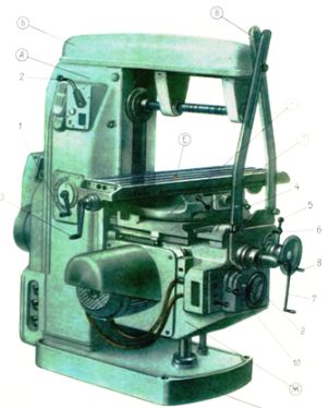
Rice. 1 Design of a universal milling machine model 6N81
The spindle head housing contains the spindle motor, gearbox and spindle for the cutter. The spindle head moves along the traverse guides along its axis, and the traverse, in turn, moves along a fixed stand having vertical guides.
Thus, the machine has three mutually perpendicular movements: horizontal movement of the table, vertical movement of the spindle head along with the traverse, and transverse movement of the spindle head along its axis. Volumetric processing is carried out using horizontal or vertical stitches. Working tools: finger cylindrical and conical or end mills.
The electrical equipment of milling machines includes a main movement drive, a feed drive, auxiliary movement drives, various electrical apparatus management, control and protection, alarm systems and local lighting of the machine.
Electric drive of milling machines
Drive of the main movement of the milling machine: asynchronous squirrel-cage motor; asynchronous motor with pole switching. Braking: counter-switching using an electromagnet. Total control range (20 - 30): 1.
Feed drive: mechanical from the main movement circuit, asynchronous squirrel-cage motor, pole-changing motor (table movement of longitudinal milling machines), G-D system (table movement and feed of heads of longitudinal milling machines), G-D system with EMU (movement tables of longitudinal milling machines); tritor drive, adjustable hydraulic drive. General control range 1: (5 - 60).
Auxiliary drives are used for: rapid movement of milling heads, movement of the crossbar (for longitudinal milling machines); clamping crossbars; cooling pump; lubrication pump, hydraulic pump.
For horizontal milling machines, flanged electric motors are usually installed on the rear wall of the bed, and for vertical milling machines, they are most often installed vertically on the top of the bed. The use of a separate electric motor to drive the feed greatly simplifies the design of milling machines. This is acceptable when gear cutting operations are not performed on the machine. Cyclic program control systems are common on milling machines. They are used for rectangular shaping. Numerical control systems are widely used for processing curved contours.
In longitudinal milling machines, separate asynchronous squirrel-cage motors and a multi-stage gearbox are usually used to drive each spindle. The speed control ranges of the spindle drives reach up to 20: 1. The control circuits for the spindle motors that are not involved in processing the part are turned off by control switches. The running spindle drive is stopped only after the feed has been completely stopped. To do this, a time relay is installed in the circuit. The feed motor can only be started after the spindle motor has been turned on.
The table drive of heavy longitudinal milling machines must provide feed rates from 50 to 1000 mm/min. In addition, it is necessary to move the table quickly at a speed of 2 - 4 m/min and slowly move when setting the machine at a speed of 5 - 6 mm/min. The total range of table drive speed control reaches 1: 600.
On heavy longitudinal milling machines, an electric drive is common. G-D system with EMU. Electric drives for vertical and horizontal (side) headstocks are similar to the table drive, but have significantly less power. If simultaneous movement of the headstocks is not required, then use a common converting unit for drives of all headstocks. Such management is simpler and costs less. Axial movement of the spindles is carried out by the same feed drive. To do this, the kinematic chain is switched accordingly. Heavy longitudinal milling machines with a movable portal also use a separate electric motor to move it.
To improve the smooth operation of some milling machines, flywheels are used. They are usually mounted on the drive shaft of the cutter. For gear hobbing machines, the necessary correspondence between the main movement and the feed movement is ensured by mechanically connecting the feed chain with the main movement chain.
Electrical equipment of gear cutting machines. Main motion drive: asynchronous squirrel-cage motor. Feed drive: mechanical from the main movement chain. Auxiliary drives are used for: rapid movement of the bracket and rear stand, movement of the milling head, single division, table rotation, cooling pump, lubrication pump, hydraulic unloading pump (for heavy machines).
Special electromechanical devices and interlocks: device for counting the number of cycles, automatic devices to compensate for dimensional tool wear.
A number of gear-processing machines use counting devices. They are used on shaving machines for counting passes, on machines for pre-cutting gears, for counting the number of divisions and for counting the number of processed parts.
In gear shaping machines, the main reciprocating movement is carried out through cranks and eccentric gears. The electrical equipment of gear shaping machines is not complicated. Apply magnetic starters with additional control of “jogs” (for adjustment). The drive is most often braked by an electromagnet.
In Fig. 2. shows the electrical circuit diagram of the milling machine model 6Р82Ш
Rice. 2. Electrical circuit diagram of a milling machine (click on the image to enlarge)
The workplace is illuminated by a local lighting lamp mounted on the left side of the machine bed. The console contains an electromagnet for fast movements. mounted on consoles on the console and the left side of the frame. All control devices are located on four panels, on the front side of which the handles of the following controls are located: S1 - input switch; S2 (S4) - spindle reversing switch; S6 - mode switch; S 3 - cooling switch. Machines 6Р82Ш and 6Р83Ш, unlike other machines, have two electric motors to drive a horizontal and rotary spindle.
The electrical circuit allows you to operate the machine in the following modes: control from handles and control buttons, automatic control of longitudinal table movements, round table. The operating mode is selected using switch S6. The feed electric motor is turned on and off from the handles acting on the limit switches for the longitudinal feed (S17, S19), vertical and transverse feed (S16, S15).
The spindle is turned on and off using the “Start” and “Stop” buttons, respectively. When you press the "Stop" button, simultaneously with the spindle motor turning off, the feed motor is also turned off. The table moves quickly when you press the S12 (S13) “Fast” button. The braking of the spindle electric motor is electrodynamic. When buttons S7 or S8 are pressed, contactor K2 is turned on, which connects the motor winding to a DC source made using rectifiers. Buttons S7 or S8 must be pressed until the motor stops completely.
Automatic control of the milling machine is carried out using cams mounted on the table. When the table moves, the cams, acting on the longitudinal feed switch handle and the upper sprocket, make the necessary switches in the electrical circuit using limit switches. The electrical circuit operates in an automatic cycle - fast approach - working feed - quick withdrawal. The rotation of the round table is carried out from the feed motor, which is started by the K6 contactor simultaneously with the spindle motor. The rapid movement of the round table occurs when the “Fast” button is pressed, turning on the contactor K3 of the high-speed electromagnet.
Expand functionality hand-held power tools, accessories for a hand-held router can make its use more convenient, comfortable and safe. Serial models of such devices are quite expensive, but you can save on their purchase and make devices for equipping a wood router with your own hands.
Various types of attachments can turn a hand router into a truly universal tool.
The main task that milling tools solve is to ensure that the tool is positioned in relation to the surface being machined in the required spatial position. Some of the most commonly used milling machine attachments come standard with milling machines. Those models that have a highly specialized purpose are purchased separately or made by hand. At the same time, many devices for a wood router have such a design that making them yourself does not present any special problems. For homemade devices for a manual router you won’t even need drawings - their drawings will be enough.
Among the accessories for a wood router that you can make yourself, there are a number of popular models. Let's take a closer look at them.
Rip fence for straight and curved cuts
A rip fence for or other base surface, which allows you to make straight cuts in wood relative to these surfaces, is one of the most popular devices and is included in the standard kit of many models. Using such a device, the base element for which, in addition to the work table, can be the side of the workpiece or a guide rail, the grooves on the workpiece are processed, and its edge part is also milled.

The design of the parallel stop for the router includes the following components:
- rods that are inserted into special holes in the milling cutter body;
- a locking screw, by means of which the rods are fixed in the required position;
- fine adjustment screw, which is needed in order to more accurately adjust the distance at which the cutter axis will be from the base surface;
- support pads with which the device rests on the base surface (in some models of parallel stops it is possible to change the distance between the support pads).
To prepare the router stop for work, you need to do the following:
- insert the stop rods into the holes in the base of the router and secure them in the required position with a locking screw;
- Loosen the locking screw and use the fine adjustment screw to adjust the distance between the cutter axis and the supporting surface of the fixture.


By adding one simple part to the rip fence, you can use this device to create not only straight, but also curved cuts in wood. Such a part is a wooden block, one side of which is straight, and on the other there is a round or angular recess. It is placed between the support pads of the stop and the base surface of the processed wood workpiece, which has a curved shape.
In this case, naturally, the straight side of the block should rest against the support pads of the device, and the side with the recess should rest against the curved base surface. You should work with a parallel stop, additionally equipped with such a block, with extreme caution, since the position of the router itself in this case will be quite unstable.

Guide rail
The guide rail, like the rip fence, ensures the linear movement of the router relative to the base surface during wood processing. Meanwhile, unlike a parallel stop, such a guide for a router can be located at any angle to the edge of the workpiece. Thus, the guide rail can provide the ability to accurately move the router during wood processing in almost any direction in the horizontal plane. A guide rail equipped with additional structural elements is also useful when milling holes located in wood at a certain pitch.
Fixation of the guide bar on the work table or workpiece is ensured by special clamps. If the basic configuration of the device does not include such clamps, ordinary clamps will be suitable for these purposes. Some models of guide bars can be equipped with a special adapter, which is often called a shoe. The adapter, connected to the base of the router via two rods, slides along the profile of the tire during processing and thus ensures the movement of the working head of the router in a given direction.

A milling device such as a guide rail is best used in conjunction with routers whose support platform is equipped with height-adjustable legs. This is explained as follows. In cases where the supporting surfaces of the router and the tire are in different horizontal planes, which can happen when the device is too close to the wood workpiece being processed, the adjustable legs of the tool make it possible to eliminate such a discrepancy.
Guide devices for equipping a router, which, despite the simplicity of their design, will be highly efficient in use, can be made with your own hands without much difficulty. The simplest of such devices can be made from a long wooden block, which is secured to the workpiece using clamps. To make this device even more convenient, you can supplement it with side stops. If you place and fix a block simultaneously on two (or even more) pieces of wood, you can mill a groove on their surface in one pass.

The main disadvantage that distinguishes the device of the above-described design is that it is not easy to accurately fix the block relative to the line of the future cut. The guide devices of the two designs proposed below do not have such a disadvantage.
The first of these devices is a device made of interconnected boards and plywood sheets. To ensure alignment of this device with respect to the edge of the groove being made, the following conditions must be met: the distance from the edge of the stop to the edge of the plywood (base) must exactly correspond to the distance at which the tool used is located from the extreme point of the router base. The device of the proposed design is used if the tree is processed with cutters of the same diameter.

For milling operations performed with tools of different diameters, it is advisable to use devices of a different design. The peculiarity of the latter is that when using them, the router comes into contact with the stop with the entire sole, and not just its middle part. The design of such a stop includes a folding board on hinges, which ensures correct spatial position devices in relation to the surface of the processed wood product. The purpose of this board is to ensure that the stop is fixed in the required position. After this procedure is completed, the board tilts back and thereby frees up space for the working head of the milling cutter.

When making such a device for a router with your own hands, you should keep in mind that the distance from the center of the tool used to the extreme point of the base of the router must correspond to the width of the folding board and the gap between the board and the stop, if it is provided in the design of the device. If in the manufacture of this device you focused only on the edge of the cutter and the edge of the groove that needs to be formed with its help, such a device can only be used with cutters of the same diameter.
Often, grooves in wood blanks have to be milled across the fibers of the material, which leads to the formation of scoring marks. The amount of scoring can be reduced by devices that, by pressing the fibers in the place where the cutter comes out, do not allow them to break off from the surface of the wood being processed. The design of one of these devices consists of two boards, which are connected to each other with screws at an angle of 90°. The width of the groove made in such a device must match the width of the recess created in the wood product, for which cutters of different diameters are used on different sides of the stop.
Another milling device, the design of which consists of two L-shaped elements, fixed to the wood product being processed with clamps, is required for milling open grooves and ensures a minimum amount of scoring during processing.
Copy rings and templates
A copying sleeve for a router is a device with a protruding edge that slides along the template and thus sets the movement of the cutter in the required direction. Such a ring can be fixed on the base of the router in various ways: screwed with screws, screwed into a threaded hole, inserted with special tendrils into holes in the base of the tool.

The diameters of the copying ring and the tool used should have close values, but it is important that the ring does not touch the cutting part of the cutter. If the diameter of the ring exceeds the transverse size of the copy cutter, then such a template to compensate for the difference between its size and the diameter of the tool should not exceed the size of the workpiece.
A milling template, made in the form of a ring, can be fixed to a piece of wood using double-sided tape and clamps, with which both parts are pressed to the work table. After milling according to the template, you should check that the ring was pressed tightly against the edge of the template during the milling operation.

Milling templates can be used not only to process the entire edge of a product, but also to give its corners a rounded shape. Using such a template for a router, you can make roundings of various radii at the corners of the wood product being processed.
Templates used to work with manual router, can be equipped with a bearing or ring. IN the latter case the following conditions must be met: the ring must exactly match the diameter of the cutter, or stops must be provided in the design of the fixture that allow the template to be moved away from the edge of the workpiece and thereby eliminate the difference between the radii of the tool and the ring.
Using templates, which can be adjustable, you can not only mill the edges of the wood product being processed, but also create shaped grooves on its surface. In addition, if you make a template of the appropriate design, which is not very difficult, you can quickly and accurately cut grooves for door hinges with it.
Cutting round and elliptical grooves
To cut grooves in the shape of a circle or ellipse in wood with a hand router, use compass devices. The simplest compass for a router consists of a rod. One end of it is connected to the base of the router, and the other is equipped with a screw and pin. The pin is inserted into a hole that acts as the center of a circle, along the contour of which a groove is formed. To change the radius of the groove circle, for which such a compass for a router is used, it is enough to move the rod relative to the base of the router. More convenient to use are compass devices, the design of which includes two rods rather than one.

Equipment operating on the principle of a compass is a fairly common type of device used to work with a router. With their help, it is very convenient to mill shaped grooves with different radii of curvature. As mentioned above, the typical design of such a device, which you can make yourself, includes a screw with a pin that can move along the groove of the device and thereby allows you to adjust the radius of the groove being created.
In cases where it is necessary to create a hole of small diameter with a milling cutter on wood or other material, a different type of equipment is used. A design feature of such devices, which are fixed on the bottom of the router base, is that their pin, installed in the central hole on the workpiece, is located under the base of the power tool being used, and not outside it.

Base Corner Guides
Centering pin Compass assembly. Bottom view Compass assembly. View from above
Using special devices, you can use a hand router to create not only round, but also oval holes in wood. The design of one of these devices includes:
- a base that can be fixed to the wood product being processed with vacuum suction cups or screws;
- two shoes that move along intersecting guides;
- two mounting rods;
- bracket connecting the base of the device to the router.
Due to special grooves in the bracket of such a device, its base plate is easily aligned in the same plane with the base of the router. If this equipment is used to perform milling along a round contour, then one shoe is used, and if along an oval contour, then both. The cut made with such a device is of higher quality than if it was made using a jigsaw or band saw. This is explained by the fact that processing with the milling cutter used in this case is carried out by a tool that rotates at high speed.

Devices for fast and high-quality milling of grooves on narrow surfaces
Anyone can answer the question of how to make grooves for door hinges or a lock. House master. For these purposes, as a rule, a drill and an ordinary chisel are used. Meanwhile, you can perform this procedure much faster and with less labor if you take a milling cutter equipped with a special device for this purpose. The design of such a device, with the help of which grooves of various widths can be created on narrow surfaces, is a flat base fixed to the base of the router. On the base, which can have either a round or rectangular shape, two pins are installed, the task of which is to ensure the straight movement of the router during processing.
The main requirement that the attachment to a milling cutter of the design described above must meet is that the axes of the guide pins must be in line with the center of the cutter used for processing wood. If this condition is met, then the groove made at the end of the workpiece will be located strictly in its center. To move the groove to one side, just put a sleeve of the appropriate size on one of the guide pins. When using a similar attachment on a hand router, you need to ensure that the guide pins are pressed against the side surfaces of the workpiece during processing.

It is possible to ensure the stability of the router when processing narrow surfaces without special devices. This problem is solved using two boards, which are attached to both sides of the workpiece in such a way as to form one plane with the surface on which the groove is made. When using this technological technique, the router itself is positioned using a parallel stop.
Milling devices for processing bodies of revolution
Many accessories for manual milling machines, made by users to suit their needs, do not have serial analogues. One of these devices, the need for which arises quite often, is a device that facilitates the process of cutting grooves in rotating bodies. Using such a device, in particular, you can easily and accurately cut longitudinal grooves on posts, balusters and other wood products of a similar configuration.

Milling cutter and frame assembly Carriage for router Dividing disc
The design of this device is:
- frame;
- mobile milling carriage;
- a disk used to set the rotation angle;
- screws that secure the workpiece being processed;
- locking screw
If such a device is additionally equipped with a simple drive, which can be used as a conventional drill or screwdriver, then milling on it can successfully replace processing performed on a lathe.
Tenon milling device
A tenon-cutting device for a router allows high-precision processing of parts connected using the tongue-and-groove principle. The most versatile of these devices allow you to mill various types of tenons (dovetail and straight). The operation of such a device involves a copying ring, which, moving along a groove in a special template, ensures precise movement of the cutter in a given direction. To make one yourself, you must first select the groove patterns for which it will be used.
Several additional options for expanding the functionality of the router
Why do you need to create additional devices to equip a hand router, which is already a fairly functional device? The fact is that such devices will allow you to turn your manual router into a full-fledged processing center. So, by fixing a manual milling cutter on a guide (this can be), you can not only make the process of using it easier, but also increase the accuracy of the operations performed. The design of such useful device does not contain complex elements, so making it for a router and drill with your own hands will not be difficult.
Many home craftsmen, wondering how to work with a hand router with even greater efficiency, make a functional work table for this tool. Naturally, such a table can also be used for other equipment (for example, circular saw or electric drill).

If you do not have a manual milling machine at your disposal, then this problem can be solved with the help of special devices that allow you to successfully perform milling on a serial lathe. Using a milling attachment for a lathe, you can significantly expand the functionality of serial equipment (in particular, use it to process planes, make grooves and grooves, and process various parts along the contour). It is also important that such a device for a lathe does not have a complicated design, and making it yourself will not be a big problem.
The operation of any modern equipment, including equipment, is impossible without electric current.
Therefore, in addition to the mechanical part of the devices, there must also be an electrical one. It is built according to a certain pattern.
Kinds
There are the following types of electrical circuits:
- structural, which determines the relationship of parts of electrical equipment;
- functional, defining electrical processes in a separate unit, completely for a CNC machine;
- the fundamental one, which reflects all the elements and gives an idea of the principle of operation;
- installation plan connections for electrical connections;
- location of parts of electrical devices, conductor and cable products.
The technical documentation of the device usually contains a circuit diagram and electrical equipment layout diagrams. It is carried out without adherence to scale and without indicating how individual elements are actually located.
General requirements for drawing up electrical circuits
Electrical diagrams of a CNC machine (we are talking about the fundamental ones) usually depict each element of electrical equipment involved in technological process or controlling its course. It is customary to place power circuits on the left, indicating a place on the diagram with a thick line, and for control circuits, they are depicted on the right side as a thin line. When drawing up a diagram, it is conventionally assumed that all circuit elements are in the off state.
The elements have a schematic representation; they are given positional designations in the form of letters. In the case of one electric motor - M, and if there are several of them - M1, M2, M3 (in letter and numerical expression). If layout diagrams are built, everything related to electrical equipment is recorded on them (in a large-scale image). There is a thin line where there is space for connecting elements - wires and cables. Such diagrams are built to represent a milling cutter; they are equipped with an electrical cabinet and a machine control panel.
As an example of a circuit for the power equipment of a numerically controlled device, one can imagine the following:

Modern electrical equipment has a very complex circuits, and reading them is not always easy. And the situation is explained by the fact that in addition to electric motors, relays, starters and contactors, the machine includes many automatic means, computer equipment, and microelectronic equipment units. Different machines, in total, have a common electrical component and, at the same time, differ in the functional features of the blocks.
Features of the electrical circuit of the 6P82 milling machine
Let's try to understand the electrical circuit of the 6P82 horizontal cantilever milling machine. It is represented by the following blocks:
- supply network with a voltage of 380 V, alternating current with a frequency of 50 Hz;
- control circuits with a voltage of 110 V ( alternating current); 65 V (DC);
- local lighting with a voltage of 24 V;
- the rated total current of simultaneously operating electric motors is 20 A and the rated current of protection devices is 63 A.
The technical documentation sets forth the limits for the use of equipment on the machine in relation to power and power loads. If it makes more than 63 rpm, then the limits of use of the main drive are limited only by the rated power of the electric motor.
It is also necessary to name the main components of the electrical circuit of milling machines: motors with drivers, interface boards, computers or laptops, power supplies and a button for emergency stop of the machine.
Self-assembly option
For those who assemble a CNC machine with their own hands, there is another option to install electrics on the machines. You can purchase a ready-made set that contains three Nema motors and the same number of drivers that fit them; step-down transformer to power the control circuit and switching board for the power supply (36 V). You can use other kits when assembling the machine yourself.
The machine electronics should be implemented on one board. The entire set of external elements is connected there, using connectors and terminal blocks:
- SD, limit switches on each axis;
- socket for turning on the main drive (DREMEL 300 is possible);
- a fan taken from a mini vacuum cleaner, a transformer for the power supply;
- connector providing connection to a PC via an LPT port.

Almost all components can be easily removed from old computer boards, Spectrums - the first PCs, as well as obsolete network switches.
The circuit includes a CNC control unit (software activation of the spindle) and is replete with additional connections for tools and sensors. The LPT computer port is connected via a standard cable. The machine electronics do not require forced cooling and do not heat up.
All electronics for the CNC are located in a niche on the rear side of the machine and are covered with a panel to prevent dust and dirt.
When dealing with electronics when assembling a CNC with your own hands, you need to choose the right power sources. For example, for SD you can use a 12 V unit and a current of 3A. A block with a voltage of 5 V with a current of 0.3A is needed to power the controller chips. How to perform power supply calculations? There is a simple formula - 3x2x1=6A, where 3 is the number of motors involved (along the X, Y and Z axes); 2 – number of powered windings, 1 A – current strength.

The design of the control controller is very simple schematic diagram, can be assembled from three microcircuits, and it does not require firmware. Therefore, a good CNC milling machine can be created by a person with little knowledge of electrical and electronics.
The SD driver controls the 4-channel amplifier. It is made of 4 transistors.
Variants of serial microcircuits are also used, such as ULN 2004 (for 9 keys), current strength 0.5 - 0.6A.
Drivers can be controlled using the vri-cnc program. You just need to find instructions on how to use it on the official website. For general control of the machine, the Kcam and Mach3 programs are used, which distinguish between different file formats for the milling and drilling process.
New approaches to machine equipment
Only reliable equipment with simple controls will ensure high-quality milling or engraving of the surfaces of parts and workpieces.
For example, planer CNC wood winner pro plans any type of wood on all four planes of the workpiece, produces various types of profiles. What is especially good about it is the principle of building in modules. This means that it is possible to change the characteristics of the equipment, maximally adapting it to the needs of customers.
In each series of machine tools, it is realistic to introduce modifications that differ in the number of spindles, have different power of electric motors, and therefore the feed rate of workpieces. The customer has the opportunity to order the layout of the machine, in accordance with the needs, with a new electrical circuit.

Therefore, before connecting the machine to the power system, it is better to check whether the parameters exactly match the network characteristics. This is the direct responsibility of the electrician. A three-phase network with a voltage of 380 V and a frequency of 50 Hz is required, grounding is required. Power cables (with a cross-section of at least 16 mm) are supplied to the equipment in a pipe or metal hose so as not to damage it during operation.
This CNC machine is the best that has been created today. It provides high-quality milling and engraving of the surfaces of parts, high precision processing of elements specified by the program (the G601 command to activate the step takes place only with precise positioning).
Conclusion
A good knowledge of electrical circuits, reading drawings - these are the skills that everyone for whom numerical and program control is not a catchy phrase, but daily work on power supply of programmable equipment and robotic equipment.
Information about the manufacturer of the cantilever milling machine 6р12, 6р12Б
Manufacturer of a series of universal milling machines 6р12, 6р12Б, founded in 1931.
The plant specializes in the production of a wide range of universal milling machines, as well as milling machines with DRO and CNC, and is one of the most famous machine-tool enterprises in Russia.
Since 1932 Gorky Milling Machine Plant is engaged in the production of machine tools and is an expert in the development and production of various metal-cutting equipment.
Universal milling machines of the P series have been produced by the Gorky Milling Machine Plant (GZFS) since 1972. The machines are similar in design, widely unified and are a further improvement of similar machines of the M series.
Today, console milling machines are produced by the company LLC "Stanochny Park", founded in 2007.
History of production of machine tools by the Gorky plant, GZFS
IN 1972 6Р 6Р12 , 6Р12Б , 6Р13 , 6Р13Б , 6Р13Ф3 , 6Р82 , 6R82G , 6Р82Ш , 6Р83 , 6R83G , 6Р83Ш .
IN 1975 year, the following copying cantilever-milling machines were put into production: 6Р13К.
IN 1978 year, copying console-milling machines were launched into production 6Р12К-1, 6Р82К-1.
IN 1985 series launched into production 6T-1 cantilever milling machines: 6Т12-1 , 6Т13-1 , 6T82-1 , 6T83-1 And GF2171 .
IN 1991 series launched into production 6T cantilever milling machines: 6T12 , 6Т12Ф20 , 6T13 , 6Т13Ф20 , 6T13F3 , 6T82 , 6T82G , 6T82sh , 6T83 , 6T83G , 6Т83Ш .
6P12 vertical cantilever milling machine. Purpose, scope
A cantilever milling machine with a vertical quill spindle has a table that moves crosswise in a horizontal plane, which is mounted on a console post that moves vertically along guides.
The 6P12 machine differs from the 6P13 machine in the installed power of the main movement and feed motors, the dimensions of the working surface of the table and the amount of table movement. High-speed machines 6Р12Б, in contrast to machines 6Р12, have an increased range of spindle speeds and table feeds and increased power of the main movement engine.
The 6P12 vertical cantilever milling machine is designed for processing all kinds of parts made of steel, cast iron, difficult-to-cut and non-ferrous metals, mainly with face and end mills. The machines can process vertical, horizontal and inclined planes, grooves, corners, frames, and curved surfaces.
For processing curved surfaces, the machine is equipped with a special copier. Processing of curved surfaces is carried out using copiers, the contour of which is felt by the tip of an electric contact sensor for table movement.
Coolant is supplied by the engine of a centrifugal vertical pump through pipelines through a nozzle to the tool.
The rotating spindle head of the machines is equipped with a mechanism for manual axial movement of the spindle sleeve, which allows processing of holes whose axis is located at an angle of up to ±45° to the working surface of the table. The drive power and high rigidity of the machines allow the use of cutters made of high-speed steel, as well as tools equipped with plates made of hard and super-hard synthetic materials.
The machines are used in single and serial production.
Machine accuracy class N according to GOST 8-77.
Russian and foreign analogues of the 6Р12 machine
FSS315, FSS350MR, (FSS450MR)- 315 x 1250 (400 x 1250) - manufacturer Gomel Machine Tool Plant
VM127M- (400 x 1600) - manufacturer Votkinsk Machine-Building Plant GPO, Federal State Unitary Enterprise
6D12, 6K12- 320 x 1250 - manufacturer Dmitrov milling machine plant DZFS
X5032, X5040- 320 x 1320 - manufacturer Shandong Weida Heavy Industries, China
FV321M, (FV401)- 320 x 1350 (400 x 1600) - manufacturer Arsenal J.S.Co. - Kazanlak, Arsenal AD, Bulgaria
Landing and connecting bases for milling machine 6Р12Б

Landing and connecting bases for milling machine 6р12Б
6Р12 General view of a vertical cantilever milling machine

Photo of a vertical cantilever milling machine 6р12
6Р12 Arrangement of components of a cantilever milling machine

Location components milling machine 6р12
- Bed - 6Р12-1
- Rotary head - 6Р12-31
- Gearbox - 6M12P-3
- Feed box - 6Р82-4
- Switching box - 6Р82-5
- Console - 6Р12-6
- Table and slide - 6Р82Г-7
- Electrical equipment - 6Р12-8

Location of controls for the 6P12 cantilever milling machine
List of controls for the 6P12 cantilever milling machine
- "Stop" button (duplicate)
- “Spindle Start” button (duplicate)
- Spindle speed indicator arrow
- Spindle speed indicator
- “Quick table” button (duplicate)
- "Spindle pulse" button
- Light switch
- Rotate the head
- Spindle sleeve clamp
- Automatic cycle sprocket
- Handle for turning on longitudinal table movements
- Table Clamps
- Handwheel for manual longitudinal movement of the table
- "Quick table" button
- "Spindle start" button
- "Stop" button
- Switch for manual or automatic control of longitudinal table movement
- Flywheel for manual lateral movements of the table
- Limb of the table transverse movement mechanism
- Vernier ring
- Handle for manual vertical movement of the table
- Button for fixing the feed switch fungus
- Feed switch mushroom
- Table feed indicator
- Table feed indicator arrow
- Handle for turning on the transverse and vertical table feeds
- Clamping the slide on the console guides
- Handle for turning on longitudinal movements of the table (duplicate)
- Handle for turning on the transverse and vertical table feed (duplicate)
- Handwheel for manual longitudinal movement of the table (duplicate)
- Spindle rotation direction switch "left-right"
- Cooling pump switch "on off"
- Input switch "on-off"
- Spindle speed shift knob
- Switch for automatic or manual control and round table operation
- Clamping the console on the frame
- Spindle sleeve extension handwheel
- Clamping the head on the frame
Kinematic diagram of the 6P12 cantilever milling machine

Kinematic diagram of a 6р12 cantilever milling machine
The kinematic diagram is given to understand the connections and interactions of the main elements of the machine. The numbers of teeth (g) of the gears are indicated on the callouts (the asterisk indicates the number of starts of the worm).
The main movement is driven by a flange electric motor through an elastic coupling.
The spindle speed is changed by moving three toothed blocks along the splined shafts.
The gearbox provides the spindle with 18 different speeds.
The feed drive is carried out from a flange electric motor mounted in the console. By means of two three-crown blocks and a movable gear wheel with a cam clutch, the feed box provides 18 different feeds, which are transmitted through a ball safety clutch to the console and then, when the corresponding cam clutch is engaged, to the screws of longitudinal, transverse and vertical movements.
Accelerated movements are obtained when the high-speed clutch is turned on, the rotation of which is carried out through intermediate gears directly from the feed electric motor.
The clutch is interlocked with the working feed clutch, which eliminates the possibility of their simultaneous activation.
Graphs explaining the structure of the machine feed mechanism are shown in Fig. 6 and 7. For machines of models 6Р12Б (Fig. 7) vertical feeds are 3 times less than longitudinal ones.
bed is the base unit on which the remaining components and mechanisms of the machine are mounted.
The frame is rigidly fixed to the base and fixed with pins.

Drawing of the rotating head of a 6р12 cantilever milling machine
Swivel head(Fig. 8) is centered in the annular recess of the bed neck and is attached to it with four bolts that fit into a single groove in the bed flange.
The spindle is a double-support shaft mounted in a retractable sleeve. The axial play in the spindle is adjusted by grinding rings 3 and 4. Increased play in the front bearing is eliminated by grinding half rings 5 and tightening the nut.
The adjustment is carried out in the following order:
- the spindle sleeve extends;
- flange 6 is dismantled;
- half rings are removed;
- a screw plug is removed from the right side of the head housing;
- through the hole, unscrewing screw 2 unlocks nut 1;
- Nut 1 is locked with a steel rod. By turning the spindle by the nut, the nut is tightened and this moves the inner race of the bearing. After checking the play in the bearing, the spindle is run in at maximum speed. When operating for an hour, the heating of the bearings should not exceed 60° C;
- the size of the gap between the bearing and the spindle collar is measured, after which the half rings 5 are ground to the required amount;
- the half rings are put in place and secured;
- Flange 6 is screwed in.
To eliminate radial play of 0.01 mm, the half rings must be ground by approximately 0.12 mm.
Rotation is transmitted to the spindle from the gearbox through a pair of bevel and a pair of cylindrical gears mounted in the head.
The bearings and gears of the rotary head are lubricated from the frame pump, and the spindle bearings and the sleeve moving mechanism are lubricated by extrusion.
Gearbox mounted directly in the frame body. The connection of the box to the electric motor shaft is carried out by an elastic coupling, allowing misalignment in the motor installation of up to 0.5-0.7 mm.
The gearbox can be inspected through the window on the right side.
The gearbox is lubricated by a plunger pump (Fig. 9), driven by an eccentric. Pump capacity is about 2 l/min. Oil is supplied to the pump through a filter. From the pump, the oil flows to the oil distributor, from which it is discharged through a copper tube to the pump control eye and through a flexible hose to the rotary head. The gearbox elements are lubricated by splashing oil coming from the holes in the oil distributor tube located above the gearbox.
Gearbox allows you to select the required speed without sequentially passing through intermediate steps.
Rack 19 (Fig. 10), moved by shift handle 18, through sector 15 through fork 22 (Fig. 11) moves the main roller 29 with shift disc 21 in the axial direction.
The shift disk can be turned by the speed indicator 23 through the bevel gears 28 and 30. The disk has several rows of holes of a certain size located against the pins of the racks 31 and 33.
The racks engage in pairs with gear 32. A shift fork is attached to one of each pair of racks. When moving the disk by pressing on the pin of one of the pair, reciprocating movement of the slats is ensured.
In this case, the forks at the end of the disk stroke occupy a position corresponding to the engagement of certain pairs of gears. To eliminate the possibility of hard stop of the gears when switching, the pins of 20 racks are spring-loaded.
Fixation of the dial when choosing a speed is ensured by ball 27, which slides into the groove of sprocket 24.
The spring 25 is adjusted by the plug 26, taking into account the clear fixation of the dial and the normal force when turning it.
Handle 18 (see Fig. 10) is held in the on position by spring 17 and ball 16. In this case, the handle tenon fits into the groove of the flange.
Correspondence of speeds to the values indicated on the indicator is achieved by a certain position of the bevel wheels along the mesh. Correct engagement is established by cores at the ends of the mating tooth and cavity or by setting the pointer to the speed position of 31.5 rpm and the disk with forks to the speed position of 31.5 rpm (for machine models 6Р12Б the corresponding speed is 50 rpm) . The gap in the engagement of the conical pair should not be more than 0.2 mm, since the disk can rotate up to 1 mm due to this.
The gearbox is lubricated from the gearbox lubrication system by splashing oil.
Feed box for milling machine 6Р12, 6Р12Б

Photo of the feed box of the 6р12 cantilever milling machine
Electrical circuit diagram of the 6P12 milling machine

Electrical circuit diagram of a 6р12 milling machine
Notes
- * - only for machines 6Р82Ш, 6Р83Ш
- ** - to the electrical diagram of the tool clamping mechanism
- *** - only for machines 6Р13Б
Electrical equipment of the 6Р12 machine
Supply network: Voltage 380 V, alternating current, frequency 50 Hz
Control circuits: Voltage 110 V, alternating current
Control circuits: Voltage 65 V, DC current
Local lighting: voltage 24 V.
Rated current (sum of rated currents of simultaneously operating electric motors) 20 A.
Rated current of the protective device (fuses, circuit breaker) at the power supply point with 63 A electricity.
Electrical equipment is made according to the following documents: circuit diagram 6Р13.8.000Э3. connection diagram of the product R13.8.000E4.
Cantilever milling machine 6P12. Video.
Technical characteristics of the cantilever milling machine 6Р12
| Parameter name | 6N12 | 6M12 | 6Р12 | 6T12 |
|---|---|---|---|---|
| Basic machine parameters | ||||
| Accuracy class according to GOST 8-71 and GOST 8-82 | N | N | N | N |
| Table surface dimensions, mm | 1250 x 320 | 1250 x 320 | 1250 x 320 | 1250 x 320 |
| Maximum mass of the workpiece, kg | 250 | 250 | 400 | |
| Distance from the end of the spindle to the table, mm | 30..400 | 30..400 | 30..450 | 30..450 |
| Distance from the spindle axis to the vertical guides of the bed (overhang), mm | 350 | 350 | 350 | 380 |
| Desktop | ||||
| Maximum longitudinal travel of the table by hand (along the X axis), mm | 700 | 700 | 800 | 800 |
| Maximum lateral movement of the table by hand (along the Y axis), mm | 240/ 260 | 240/ 260 | 250 | 320 |
| Maximum vertical travel of the table by hand (along the Z axis), mm | 370 | 370 | 420 | 420 |
| Limits of longitudinal table feeds (X), mm/min | 40..2000 | 12..1250 | 12,5..1600 | 12,5..1600 |
| Limits of table cross feeds (Y), mm/min | 27..1330 | 12..1250 | 12,5..1600 | 12,5..1600 |
| Limits of vertical table feeds (Z), mm/min | 13..665 | 8,3..416,6 | 4,1..530 | 4,1..530 |
| Number of feeds longitudinal/transverse/vertical | 18 | 18 | 22 | 22 |
| Speed of fast longitudinal movements of the table (along the X axis), m/min | 4 | 3 | 4 | 4 |
| Speed of fast transverse movements of the table (along the Y axis), m/min | 4 | 3 | 4 | 4 |
| Speed of fast vertical movements of the table (along the Z axis), m/min | 1 | 1 | 1,330 | 1,330 |
| Spindle | ||||
| Spindle speed, rpm | 63..3150 | 31,5..1600 | 40..2000 | 31,5..1600 |
| Number of spindle speeds | 18 | 18 | 18 | 18 |
| Spindle quill movement, mm | 70 | 70 | 70 | 70 |
| Milling spindle taper | №3 | №3 | №3 | №3 |
| Spindle end GOST 24644-81, row 4, version 6 | 50 | |||
| Milling spindle hole, mm | 29 | 29 | 29 | |
| Rotate the spindle head right and left, degrees | ±45 | ±45 | ±45 | ±45 |
| Machine mechanics | ||||
| Feed stops (longitudinal, transverse, vertical) | Eat | Eat | Eat | Eat |
| Manual locking and mechanical feed(longitudinal, transverse, vertical) | Eat | Eat | Eat | Eat |
| Blocking separate feed switching | Eat | Eat | Eat | Eat |
| Spindle braking | Eat | Eat | Eat | Eat |
| Overload safety clutch | Eat | Eat | Eat | Eat |
| Automatic intermittent feed | Eat | Eat | Eat | Eat |
| Electrical equipment, drive | ||||
| Number of electric motors on the machine | 3 | 3 | 3 | 4 |
| Main motion drive electric motor, kW | 7 | 7,5 | 7,5 | 7,5 |
| Feed drive electric motor, kW | 1,7 | 2,2 | 2,2 | 3,0 |
| Tool clamping motor, kW | - | - | - | 0,25 |
| Coolant pump electric motor, kW | 0,12 | 0,12 | 0,12 | 0,12 |
| Total power of all electric motors, kW | 9,825 | 9,825 | 1,87 | |
| Dimensions and weight of the machine | ||||
| Machine dimensions (length width height), mm | 1745 x 2260 x 2000 | 2395 x 1745 x 2000 | 2305 x 1950 x 2020 | 2280 x 1965 x 2265 |
| Machine weight, kg | 3000 | 3000 | 3120 | 3250 |