Automatic machines are two-pole and pole. Detailed instructions on how to connect a circuit breaker
It is difficult to imagine a distribution board without modern modular protection devices, such as circuit breakers, devices protective shutdown, differential circuit breakers and all kinds of protection relays. But these modular devices are not always connected correctly and reliably.
In view of servicing electrical panels, I sometimes have to deal with errors in connecting the circuit breakers that are installed in them. It would seem, how can you connect an ordinary single-pole circuit breaker incorrectly? I stripped the cable to a certain length, inserted it into the terminals, and tightened the screws securely.
But no matter how strange it may sound, most people have “clumsy” hands and the build quality of the shields leaves much to be desired. Although in fact we all make or have made mistakes in one industry or another, and as the famous proverb says: “he who does nothing makes no mistakes.”
I welcome all friends to the “Electrician in the House” website. In this article we will look at and analyze several options for the most common and serious mistakes.
Connecting machines in the panel - entrance from above or below?
The first thing I would like to start with is the correct connection of the machine in principle. As is known circuit breaker has two contacts for connecting movable and fixed. Which pin should be connected to the top or bottom? To date, there has been a lot of controversy regarding this matter. There are a lot of questions and opinions on this matter on any electrical forum.
Let's turn to for advice regulatory documents. What does the PUE say about this? In the 7th edition of the PUE, clause 3.1.6. said:
As you can see, the rules say that supply wire when connecting machines in the shield should be connected, as a rule, to fixed contacts. This also applies to all ouzo, difavtomat and other protection devices. From this entire clipping, the expression “as a rule” is not clear. That is, it seems to be as it should be, but in some cases there may be an exception.
To understand where the moving and fixed contacts are located, you need to imagine the internal structure of the circuit breaker. Let's use the example of a single-pole circuit breaker to look at where the fixed contact is located.

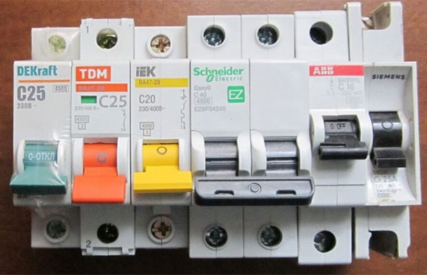
Before us is an automatic machine of the BA47-29 series from iek. From the photo it is clear that its fixed contact is the upper terminal, and the moving contact is the lower terminal. If we consider electrical symbols on the switch itself, then here you can also see that the fixed contact is on top.

Circuit breakers from other manufacturers have similar markings on the housing. Take, for example, a machine from a company Schneider Electric Easy9, its fixed contact is also located on top. For Schneider Electric RCDs, everything is similar on top there are fixed contacts and moving ones below.


Another example is safety devices from Hager. On the housing of the hager circuit breakers and RCDs you can also see symbols, from which it is clear that fixed contacts are on top.
Let's figure out whether it makes sense from the technical side, how to connect the machine from above or below.
The circuit breaker protects the line from overloads and short circuits. When overcurrents occur, the thermal and electromagnetic releases located inside the housing react. From which side the power will be connected from above or below to trigger the releases there is absolutely no difference. That is, we can say with confidence that the operation of the machine is not affected by which contact the power is supplied to.
In truth, I should note that manufacturers of modern “branded” modular devices, such as ABB, Hager and others, allow power to be connected to the bottom terminals. For this purpose, the machines have special clamps designed for comb tires.
Why do the PUE recommend connecting to fixed contacts (top)? This rule was approved for general purposes. Any educated electrician knows that when performing work it is necessary to remove voltage from the equipment on which he will work. When “climbing” into the shield, a person intuitively assumes the presence of a phase at the top on automatic machines. Having turned off the AV in the panel, he knows that there is no voltage at the lower terminals and everything that comes from them.
Now let’s imagine that Uncle Vasya, an electrician, did the work for you and connected the phase to the lower AB contacts. Some time has passed (a week, a month, a year) and you have a need to replace one of the machines (or add a new one). Electrician Uncle Petya comes, turns off the necessary machines and confidently reaches into the voltage with his bare hands.
In the recent Soviet past, all machine guns had a fixed contact at the top (for example, AP-50). Nowadays, based on the design of modular AVs, you can’t tell where the movable and where the fixed contact is. For the ABs that we discussed above, the fixed contact was located on top. Where are the guarantees that Chinese machines will have a fixed contact located on top?
For those who do not agree with me, the question is why on electrical diagrams The power supply to the machines is connected precisely to the fixed contacts.
If we take, for example, a regular switch of the RB type, which is installed at every industrial facility, then it will never be connected upside down. Connecting power to switching devices of this kind relies only on the upper contacts. I turned off the switch and you know that the lower contacts are without voltage.
We connect the wires to the machine - a cable with a monolithic core
How do most users connect machines in the control panel? What mistakes can be made in this case? Let's look at the most common errors here.
Error – 1. Insulation coming into contact.
Everyone knows that before you need to remove the insulation from the connected wires. It would seem that there is nothing complicated here, I stripped the core to the required length, then we insert it into the clamping terminal of the machine and tighten it with a screw, thereby ensuring reliable contact.
But there are cases when people are perplexed why the machine burns out when everything is connected correctly. Or why the power in the apartment periodically disappears when the wiring and filling in the panel are completely new.

One of the reasons for the above contact with wire insulation under the contact terminal of the circuit breaker. Such a danger in the form of poor contact carries the threat of melting of the insulation, not only of the wire, but also of the machine itself, which can lead to a fire.
To eliminate this, you need to monitor and check how the wire is tightened in the socket. Correct connection circuit breakers in the distribution board should exclude such errors.
Error - 2. You cannot connect several wires of different sections to one AB terminal.
If the need arises connect several machines standing in the same row from one source (wire), a comb bus is ideally suited for this purpose. But such tires are not always at hand. How to combine several group machines in this case? Any electrician, answering this question, will tell you to make homemade jumpers from cable cores.


To make such a jumper, use pieces of wire of the same cross-section, or better yet, do not break it along its entire length. How to do it? Without removing the insulation from the wire, form a jumper of the desired shape and size (according to the number of branches). Then we strip the insulation from the wire at the bend to the required length, and we get an unbreakable jumper from a single piece of wire.

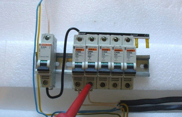
An example of connecting circuit breakers with jumpers from different cable sections. The first machine receives a “phase” with a 4 mm2 wire, and the other machines already have jumpers with a 2.5 mm2 wire. The photo shows that jumper made of wires of different sections. As a result, poor contact, increased temperature, melting of insulation not only on the wires, but also on the machine itself.

For example, let's try to tighten two wires with a cross section of 2.5 mm2 and 1.5 mm2 into the terminal of the circuit breaker. No matter how hard I tried to ensure reliable contact in this case, nothing worked. A wire with a cross section of 1.5 mm2 was hanging loosely.


Another example in the photo is a difavtomat, into the terminal of which they plugged two wires of different sections and tried to tighten the whole thing securely. As a result, the wire with a smaller cross-section dangles and sparks.

Error – 3. Formation of the ends of wires and cables.
This point most likely refers not to an error, but to a recommendation. To connect the cores of outgoing wires and cables to the machines, we remove the insulation from them by about 1 cm, insert the bare part into the contact and tighten it with a screw. According to statistics, 80% of electricians make connections this way.


The contact at the junction is reliable, but it can be further improved without wasting time and money. When connecting to machines cables with solid core make a U-shaped bend at the ends.


This formation of the ends will increase the area of contact of the wire with the surface of the clamp, which means the contact will be better. P.S. The inner walls of the AB contact pads have special notches. When the screw is tightened, these notches cut into the core, thereby increasing the reliability of the contact.

Connecting stranded wires to the machine
For wiring panels, electricians often prefer a flexible wire with a stranded core of type PV-3 or PuGV. It is easier and easier to work with than with a monolithic core. But there is one peculiarity here.
The main mistake that beginners make in this regard is connecting stranded wire to the circuit breaker without termination. If you crimp a bare stranded wire as it is, then when tightening, the strands are crushed and break off, and this leads to a loss of cross-section and deterioration of contact.


Experienced “specialists” know that it is impossible to tighten a bare stranded wire into a terminal. And for terminating stranded conductors, you need to use special tips NShV or NShVI.

In addition, if there is a need to connect two stranded wires to one terminal of the machine for this you need to use a double tip NSHVI-2. Using NSHVI-2 it is very convenient to form jumpers for connecting several group circuit breakers.
Soldering wires to the terminal of the machine - ERROR (error)
Separately, I would like to dwell on this method of terminating wires in a shield, such as soldering. Human nature is such that people try to save money on everything and do not always want to spend money on all kinds of tips, tools and all sorts of modern small things for installation.
For example, consider the case when an electrician from the housing office, Uncle Petya, performs wiring electrical panel multi-core wire (or connects outgoing lines to the apartment). He does not have NShVI tips. But you always have a good old soldering iron at hand. And the electrician, Uncle Petya, finds no other way out than to tin the multi-wire core, pushes the whole thing into the contact clamp of the machine and tightens it with a screw. Why is this dangerous?


When assembling distribution boards, DO NOT solder or tin the stranded core. The fact is that a tinned connection begins to “float” over time. And for such contact to be reliable, it must be constantly checked and tightened. But as practice shows, this is always forgotten. The soldering begins to overheat, the solder melts, the joint weakens even more and the contact begins to “burn out.” In general, such a connection can lead to a FIRE.


Therefore, if a stranded wire is used during installation, then NShVI lugs must be used to terminate it.
The question that worries everyone caring owner– how to correctly and safely connect circuit breakers in an electrical panel. The process is, of course, delicate, but at the same time easy to do. Power must be connected to the top contacts. These are general rules security. DIN rails are installed in a free space - this is a metal profile that is used in electrical engineering for fastening. The location on the rail is not fundamental to the operation of the equipment.
Modern modular protection systems are called, which are designed to protect electrical appliances from dangerous influences. electric current. We can highlight:
- residual current device;
- switch;
- differentiated device;
- protective relay.
The machines are different, but they serve the same purpose.
These are the main varieties that are used in everyday life to turn off electrical energy when:
- if a current of greater voltage begins to flow through the circuit than that for which the system is designed;
- a short circuit has occurred.
Before studying the connection of machines in the panel, it is important to understand that in modern houses and apartments have a large amount of electrical equipment installed. If the network fails, expensive refrigerators, microwaves, electric ovens, washing machines, etc. may be damaged. If
Electric machines: how to choose a quality one
Installation is a secondary matter.
Before you connect the machine in the panel, you need to purchase it. Experts say: choosing a unit with excellent characteristics is 80 percent of success in its operation.
What to focus on:

A high-quality RCD is certified and licensed
- For the price. There is no need to skimp on equipment. This is the thing that is installed for many years. It is advisable to choose a proven brand that has proven itself well in the market.
Among the leaders are manufacturing companies EKF, IEK, Merlin Green, ABB. If the price is less than 500 rubles, the product is not worth purchasing.
- For frequency and rated voltage. Choose one that is designed to operate with current at a frequency of 50 hertz. It can be used in single-phase and three-phase circuits as desired. This option can be called optimal for use in a separate apartment or private residential building.
- Rated current value. It tells the owner how much current (in amperes) can flow through the device regularly. If the value is exceeded, a power outage will occur in the selected section of the circuit.
- Poles (number). It is possible to connect the machines in the panel yourself to a single-phase and three-phase network. We have already mentioned this. If there are one or two poles, then you can connect it to a 220-volt network; if there are three or four, then to a 380-volt network.
- The number of poles is equal to the number of places for devices. Knowing this principle, it will be easier to understand how the circuit diagram for connecting the machines in the panel works.
Connection: Tools Required
It is not possible to connect the equipment with bare hands without any additional devices. In order to connect to the network, you need to have at least the following tools:
- indicator screwdriver;
- stripper for removing insulation;
- wire cutters;
- various pliers;
- screwdrivers;
- crimper for crimping lugs (if multi-core wiring is used).
Any circuit breaker is installed on a DIN rail. Its width is standard - 3.5 centimeters.
How to connect correctly: work order
You have already chosen the device, stocked up on the necessary tools, which means you can install the machines in the panel. If you follow strict sequence and all safety measures, the procedure will be completed quickly and safely for the health and life of the installer. The order of work looks like this:
- de-energize the electrical panel. Check if there is electricity using an indicator screwdriver;
- take care that there is no unexpected power cut;
- snap the equipment onto the DIN rail;
- take care of secure fixation. He shouldn't move;
- if there is only one pole, then the circuit phase comes out from the bottom of the terminal, and the device phase comes out from the top of the terminal;
- if there are two poles, then the same phases are supplied to the terminals on the top and bottom left, and zero is supplied to the bottom and top terminals on the right. This is how the zero bus in the panel is determined;
- if there are three poles, then the input and output of the phases must be determined in a clear sequence. They are oriented by the letters of the Latin alphabet, which are printed below and above: A, B, C or L1, L2, L3 (depending on the unit itself);
- if there are four poles, then the additional terminal is used for zero;
- Electricians' opinions on how to properly connect a machine from above or below are sometimes divided. Experienced specialists advise fastening incoming lines from above, and outgoing lines from below. This is a generally accepted system that will help avoid emergencies when replacing equipment in the near or distant future;
- When connecting, there should be no kinks on the cables, in which case the system will not work normally, failures and inaccuracies are possible;
- excess parts of the power lines must be removed with pliers;
- next you need to remove the insulation from the end of the cable, if any;
- If the cable is multi-core, then the lugs must be terminated. These are the basic safety requirements;
- check the correct connection and reliability of fastening on the DIN rail;
- install the cable into the terminals and secure with a screwdriver. Tightening too much can be dangerous for the unit. There is no need to be zealous in this case;
- Apply voltage;
- check if there is voltage. You can check it using an indicator screwdriver.

It is important to connect the machines in series so as not to disrupt the network
You can connect according to the following diagrams:
1) meter – unit – consumers;
2) counter – group unit – switch – groups of units – consumers.
In the first case, when the device is triggered, the entire network will shut down, in the second, only the specific part where the emergency occurred.
The main mistakes of novice electricians
Not often, but it happens that the circuit breaker after installation does not perform its “ professional responsibilities" We have already figured out how to install the machine in the dashboard, now it is important to understand why it does not want to work. Common installer mistakes include:
- The insulation has come into contact. The insulation from electrical wires must be removed; If this is not done, then there is a possibility of a short circuit. At a minimum, failure in this case is guaranteed.
- Connecting several wires with different cross sections to one terminal. This happens when we are talking about connecting a group of units. In this case, it is advisable to use jumpers between devices and cables to avoid confusion. Jumpers must be made from a cable with a similar cross-section to the wires. This will help avoid premature melting of the jumpers and fire.
- An attempt to form the ends of the veins. Before inserting it into the terminal, the exposed part of the line must be bent into a U shape. The area of contact of the wire with the surface will increase, the performance of the device will increase, and the contact will become more reliable.
- Connecting a wire with several cores to the unit without termination. The exposed veins will be crushed and they will not be able to work normally.
- Soldering a cable with several cores. This is not recommended due to premature wear of the cores in the future.
How to install a machine in a panel: safety rules
There are some special features when installing in a panel. You cannot work with bare hands. It is important to protect yourself by wearing special protective gloves.
Often those who install the unit themselves are interested in how to connect machines after the meter. In fact, the process is no different from placing the equipment before the meter. The connection can be made according to two schemes. The main thing is to strictly follow the order and turn off the power to the electrical panel before installation.
Another controversial issue is connecting the machine in the panel from below or from above. There is no need to reinvent the wheel. In the world of electricians, the rule is: entry is from above, exit from below. If one person installs the device incorrectly, then another may end up in a hospital bed due to such negligence! Therefore, we must act strictly according to the principle.
There should be no problems with how to connect a single-phase circuit breaker. The unit has one or two terminals at the top or bottom. The left ones on top are designed for current input and output, the right ones are designed for zero.
The installation of the machine in the panel is shown in the following video:
During operation
What to do if the unit works? How to reconnect the circuit breaker? There is no need to remove it from the DIN rail. But you shouldn’t turn it on manually right away either. It is important to understand why the device reacted? What is the reason?
You can turn it on again no earlier than after 10 minutes so that the device can cool down and recover.
The unit can operate when a large number of household appliances are used simultaneously in an apartment or house. To protect the network from overvoltage and short circuits, the switch performs its functions. How to calculate the load on the machine? The maximum voltage is indicated on the equipment itself. You need to calculate how much electricity household appliances consume in total, and compare this figure with the one indicated on the circuit breaker. How to calculate the amperage of a machine? For example, washing machine, air conditioning and electric stove together they consume about 450 amperes, while the differential device can only pass 400 amperes. This means that when connected to the network at the same time, it will trigger.

An electrician's work must be safe.
Emergency operation may occur in hot weather. This happens extremely rarely. But there is a possibility. If the area gets too hot, the additional heat energy will “confuse” the unit. Most often this happens if the equipment is too old and does not meet modern requirements. Therefore, before connecting the circuit breaker, make sure that the electrical panel itself complies with modern requirements and standards. If this is not the case, then before connecting the machine to the wiring, take care to replace the old panel with a new one. There shouldn't be any problems in this case. There is no shortage in this area.
Finally

Machines in the panel must be located in strict order
Strict adherence to connection technology should be fundamental in the installation process. To the question of how to connect an automatic packet machine, there will be one answer - most importantly, it’s safe. Incorrect installation can lead to fire and breakdown not of a single device, but of the entire electrical circuit and a large number of household appliances. To avoid such troubles, it is enough to take your time, perform actions consistently, using high-quality tools.
You can learn more about installation from the video:
Greetings, dear readers of the site.
In continuation of the series of publications on circuit breakers, the next article in the series is circuit breaker connection diagram.
Let me remind you that a series of articles is included in the course.
We have already studied in detail the design and main specifications machines, let's look at their connection diagrams.
Depending on the number of switched poles (or otherwise modules), the machines are divided into one-, two-, three-, four-pole (three phases and zero). In the event of an emergency, all poles of the circuit breaker are switched off simultaneously.
One pole is a part of the machine that includes two screw terminals for connecting wires (supply side and load side). The width of a single-pole circuit breaker installed on a DIN rail is standard - 17.5 mm; multi-pole circuit breakers are multiples of this width.
Single- and double-pole are used in a single-phase electrical network. Most often, single-pole circuit breakers are used; they are installed in a phase wire break and, in the event of an emergency, disconnect the supply phase from the load.
Two-pole circuit breakers allow you to simultaneously disconnect both zero and phase. They are most often used as introductory machines, or if it is necessary to completely disconnect the consumer from the electrical network, for example, a boiler or shower. They disconnect zero and phase from the protected section of the circuit and allow for repair, maintenance or replacement of circuit breakers.
You cannot install two single-pole circuit breakers separately to protect the phase and neutral wires. For these purposes, two-pole circuit breakers are used, which turn off zero and phase simultaneously.
Three- and four-pole are used in a three-phase electrical network. Three-pole circuit breakers are installed in the phase break (L1, L2, L3) of a three-phase network and are used to connect a three-phase load (electric motors, three-phase electric stoves, etc.) to it. In the event of an emergency, they simultaneously disconnect all three phases from the load.
Four-pole circuit breakers allow you to simultaneously disconnect both zero and all three phases, and are used as input circuit breakers in a three-phase electrical network.
Allows you to disconnect all electrical wiring of the apartment and disconnect the supply line from the group electrical circuits of the apartment.
Depending on the grounding system, the following input circuit breakers are used:
The input circuit breaker for the TN-S system (where the zero working N and zero protective PE conductors are separated) must be:
- single-pole with zero or double-pole;
- three-pole with neutral or four-pole.
The TN-S system is used in modern homes.
This is necessary to simultaneously disconnect the apartment’s electrical network from the neutral working and phase conductors on the power input side, since the neutral and protective conductors are separated along their entire length.
For the TN-C system (where the neutral working and neutral protective conductors are combined into one PEN conductor), the input circuit breaker is installed single-pole (with a power supply of 220 V) or three-pole (with a power supply of 380 V). They are installed in the gap of the phase working conductors.
The TN-C system is used in Soviet-built houses (the so-called “double wiring”).
According to the rules for electrical installations (clause 1.7.145), it is not allowed to connect switching devices in circuits of PE and PEN conductors, with the exception of cases of powering electrical receivers using plug connectors.
This requirement of the PUE is due to the fact that a situation is possible when two-pole circuit breakers will not be able to simultaneously disconnect the phase and PEN conductors. And by disconnecting the PEN conductor, we thereby initiate its break.
When switched on under load, sticking of phase contacts may occur inside the machine (for example, a grain of sand may fall on the contact group of the machine); in this case, when the machine is disconnected from the supply network, the PEN conductor will break and dangerous potential will be carried to the grounded electrical equipment housings. Those. there is no guarantee that the switching devices will simultaneously disconnect both the phase and PEN conductors.
The connection of wires to circuit breakers is carried out according to the scheme: “power from above”, and “load from below”. Those. the wire with the supply voltage is connected to the upper screw terminal, and the outgoing load wire to the lower screw terminal.
Look detailed video Circuit breaker connection diagrams
We examined the design, main characteristics, and connection diagrams of circuit breakers and came close to the issue of their selection.
Subscribe to the news, the most interesting is ahead!
Connecting circuit breakers
Connections of machines in a single-phase network
The installation option for circuit breakers depends on the selected single or three-phase network.
For a single-phase network, one or two-pole circuit breakers are used; for a three-phase network, three or four-pole circuit breakers are used. Multi-pole circuit breakers are assembled from several single-pole circuit breakers.
The protection mechanism is connected into one system through special connections. For example, when the network of one pole of the machine is disconnected due to overload or short circuit. the entire multi-pole circuit breaker will turn off. A phase is connected to a single-pole circuit breaker; in the event of an accident, the circuit breaker turns off the phase.
This option for connecting the machine is suitable for a TN-C system network, where the neutral wire is connected separately, through the neutral bus. If the house uses the TN-S system, then the input is made by three wires, phase, zero - blue wire and yellow-green PEN protective grounding wire.

Connecting single-pole circuit breakers in a TN-S network system with neutral and protective grounding
In this situation, the installation of circuit breakers is carried out on two-pole circuit breakers, where the phase and neutral are connected to the upper terminals of the input circuit breaker, and the protective yellow-green wire PEN is connected to the grounding bus in the electrical panel.

Use of two-pole circuit breakers in a TN-S network system with neutral and protective grounding
Connecting machines in a three-phase network
In a three-phase network, three or four-pole circuit breakers are used. In the TN-C system, all three phases L1, L2, L3 are connected to the upper terminals of a three-pole circuit breaker, and the neutral wire is connected to the neutral bus of the electrical panel.

Connecting a three-pole circuit breaker in a TN-S network system with neutral and protective grounding
In the TN-S system, three phases are connected to the upper terminals of a four-pole circuit breaker, and the blue neutral wire is connected to the upper terminal of the fourth pole of the input circuit breaker marked N. The yellow-green protective PEN wire is connected to the grounding bus of the electrical panel.
Connecting wires to the machine
The installation of the circuit breaker is carried out on a DIN rail, the length of which is selected at the rate of 17.5 millimeters per single-pole circuit breaker. When installing a cable, 10–15 cm of outer insulation is removed from it to improve the flexibility of the wires and ease of installation.
The ends of the wires are protected by 7-10 mm and placed under the terminal contacts. There is no need to tightly tighten the screw connections of the machine to avoid distortion of its mechanisms. When installing wires into the terminals of the machine, make sure that the insulation of the wires does not get under the contacts. In the best case, there will be an unreliable connection, and in the worst case, the phase on the contact will be lost.

Mounting connection rail for automatic machines
For a multi-core cable, to ensure reliable contact, it is better to install copper lugs of the appropriate size. In an electrical panel where several circuit breakers are installed in a row, it is convenient to install a copper connecting bar for circuit breakers (comb). It is cut to the required length and installed in the required sequence instead of wire jumpers.
An ordinary person is unlikely to know how to connect a circuit breaker. After reading this article, you will learn what machines are needed for, how to determine exactly where they are located and what to do if they work.
Circuit breaker - why is it needed?
The purpose of the machines is to switch electrical circuits, that is, to turn them off and on if necessary. Having carefully examined this device, you will notice a small lever with which the apartment owner can turn off or turn on the electrical circuit. However, the name contains the word “automatic”, which hints to us that the operation is automatic.
This happens in one of two cases:
- The flow of current through the circuit exceeds the permissible limits. The shutdown may not occur immediately, but the higher the value, the faster the device will turn off the electrical circuit.
- In case of short circuit. Then the operation occurs instantly, within a few fractions of a second.
For every person who is going to make the connection with their own hands electric machines in the shield, when working you must be as careful and attentive as possible, avoid contact with exposed wires and follow all electrical and fire safety rules.
Buying vending machines - what you should pay attention to
A correctly selected device is the key to reliable operation of all electrical appliances in your apartment, so you need to approach your choice responsibly. Ideally, seek help from an electrician who will tell you which model is suitable in your case. If such an opportunity did not arise, then the next chapter is especially for you.
So, all the characteristics that matter when choosing a device are indicated on the product label. First, pay attention to the brand, which is usually located at the top of the machine panel. There is no need to save money when purchasing; give your preference to proven brands, for example, EKF, IEK, Schneider Electric, Merlin Green, Hager, Legrand, ABB. These manufacturers produce high-quality products that are distinguished by excellent performance characteristics, as well as reliability and long service life.
Frequency and voltage rating are another important consideration. In most cases, the inscription “220/400V/50Hz” is found, which means that the device is designed to operate with a current of 50 Hz in single-phase and three-phase circuits. This is the most best option for any apartment owner, as it is ideal for ensuring reliable protection for everyone modern devices and devices.
One of the most important parameters is the rated current. She points maximum value current in amperes flowing through the circuit breaker for a very long time without turning it off. If the rated current value is exceeded, the thermal release is activated, which disconnects the machine from the network. The greater the excess, the sooner the device will operate. It should be remembered that the rated current is selected in accordance with the cross-section of the wire or cable, but not the load power. In this case, the switch prevents the wires from overheating during the flow of electric current.
Another significant factor is the number of poles. In private houses and modern apartments, switches with a number of poles from one to four are used. Single-pole and double-pole devices are used in single-phase circuits, the rest are used to protect three-phase circuits. The number of modules, or places for machines, fully corresponds to the number of poles. There are 17.5 mm per module.

To avoid problems with how to properly connect circuit breakers in an electrical panel, you need to follow two simple rules:
- The rating of the machine should be determined based on the cross-section of wires and cables, but not the load.
- Cable cross-section corresponds to maximum load when included in electrical network devices.
Connection tools - what we need
Installing circuit breakers is a rather complicated process, but with due care, anyone can perform all the operations. Opening the switchboard, you see that the electrical equipment is attached to a special DIN rail using a special latch. The width of this rail is 35 mm.
- Indicator screwdriver
- Stripper - a special tool used when stripping insulation
- Cable cutter or regular wire cutters
- Pliers of various sizes
- Phillips and slotted screwdriver set
- Crimper - a device for crimping tips when working with stranded wires.
Connection process - do it yourself
All necessary tools we have at hand, a device corresponding to the performance of the electrical circuit has also already been purchased. All that remains is to find out how to properly connect the machine in the electrical panel. First of all, it is necessary to completely de-energize the electrical panel, and also take measures to prevent the voltage from suddenly turning on. To make sure there is no mains voltage, use an indicator screwdriver.
The process of installing the machine itself is very simple; you just need to snap the device into any free space on the DIN rail. If there are empty spaces for new modules on the left or right, you should use a limiter, the task of which is to ensure that the static counter remains stationary. The following order is slightly different, depending on the number of poles:
- If a single-pole switch is connected, the phase of the protected circuit must go from the lower terminal, and the phase of the RCD or input device must go to the upper terminal.
- Two-pole circuit breakers are not much different, since similar phases are supplied to the upper and lower left terminals, while zero is supplied to the right terminals and, accordingly, also zero is removed.
- Three-pole switch - the upper phases are supplied based on their order, from left to right - A, B, C (L1, L2, L3). The phases leave in a similar order from the bottom of the device.
- A four-pole device is practically no different from a three-pole device. Only one right terminal is added at the top and bottom, which serve for zero pass.
It should be remembered that only incoming wires are attached to the upper terminals, while outgoing ones are installed on the lower ones. When laying wires, it is necessary to avoid sharp turns. This is due to the fact that in the future, creases may appear, causing power failures. After laying the wires, the length required for normal free entry into the terminal is measured, and the excess part is removed using wire cutters.
A prerequisite is compliance with all safety regulations! Electricity is no joke; it’s better to be on the safe side than to end up in a hospital bed.
Now a stripper is used, with which we remove insulating material from the end of the cable by 10 mm. When working with regular wires, you can proceed to the next step, but if you purchased multi-core cables, then it is imperative to terminate their tips using a crimper. If you do not have this tool, then working with stranded wires is strictly prohibited.

Having completed all the basic steps, it is recommended to once again check that the circuit breaker is connected correctly and whether the result of your efforts corresponds to the circuit diagram of this panel. Next, you need to place the cables in the terminals of the machines and clamp them with a screwdriver. It is not recommended to tighten it all the way as hard as possible, as this may damage the body of the device.
All that remains is to apply voltage, turn on all protective devices and check the voltage at the output and input of the machine using an indicator screwdriver. At this point the installation can be considered complete. Outwardly, everything seems quite simple and very fast, but in reality it will take a lot of time and effort to achieve the desired result, especially if you did not know how to connect the machine in the panel and are doing it for the first time.
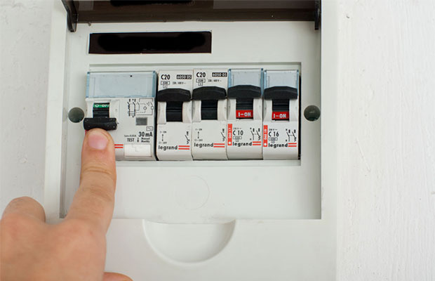
The switch has tripped - what to do?
There are some important points to note when operating the machines. For example, what to do if the device suddenly works and cuts off the power supply. It is necessary to find out the cause of the problem and, if possible, eliminate its source. Although most people are in a hurry to immediately turn on the device again, which is fundamentally wrong. If only because when turned off, severe overheating of the internal components occurs, especially the solenoid and the bimetallic plate of the thermal release. You should wait about ten minutes for the device to return to normal operating temperatures, after which you can try turning it on.
During these ten minutes, you can walk around the house or apartment in order to detect faults. You need to carefully inspect all household appliances connected to the network, as well as sockets. Hot plugs, darkening from exposure to fire, and the appearance of a characteristic burnt smell indicate the source of the circuit breaker shutdown.
If there are several machines, you need to turn them on sequentially to localize the problem area. Thus, problems such as turning off the input machine may appear, which makes it possible to identify a specific electrical circuit. In this case, you should find the device that led to the short circuit, which may be a burnt-out lamp with a shorted filament or melted insulation.
The procedure is simple: turn off the machine and disconnect from the network all devices that consume energy from this network, then turn on the switch. If it works, then the problem is definitely in one of the household appliances. Otherwise, there are violations in the wiring or connection diagram, then it is recommended to call an electrician, since it will be very difficult to correct the situation on your own.
The most common reason Triggering is the simultaneous activation of a large number of devices or the connection to the network of equipment that consumes too much electricity. For example, the air conditioner is turned on at the same time, washing machine, oven or powerful heater. Naturally, the machine is not able to cope with the multiple increased load, which results in its shutdown. The solution to the problem is as simple as possible - turn off some devices to reduce the load on the network.
Problems may occur in hot summer weather. The reason for this is the additional effect of thermal energy on the device, which can lead to shutdown. As practice shows, such phenomena occur only with old devices, while modern devices practically immune to external weather conditions. This once again brings us back to the fact that you need to buy only high-quality machines from the best manufacturers.

