Homemade wood lathe made from corners. Homemade machines and devices for the home workshop: we make them ourselves
The availability of lathes for free sale has allowed many craftsmen to use their skills and potential to manufacture various products. Previously, and it’s true, it was almost impossible to buy a machine for your home. There are currently many on sale different models from Russian and foreign manufacturers. Mainly Russian-Chinese(idea and patent Russia, made in China) and Swiss - Chinese machines. These are brands such as Kraton, Zubr, Enkor, related to desktop machines, with a power of about 350 W and a price from 7,400 rubles to 9,000 rubles.
 Machine ENCOR Corvette-73 with a power of 350 W and a price of 7800 rubles
 Jet JML machines have a higher price, but they also differ in quality with the same difference as comparing prices. There are options for both tabletop and floor-standing machines, with good quality assembly and excellent cast frame. The average price with a power of 500 W, which is quite enough for working with wood, starts from 25,000 rubles.
 The Jet JML lathe is a pleasure to work with
 The price for a good machine is worth it good money. But rather than buying an inexpensive Zubr type machine and finishing and improving it with your own hands, many people wonder if it’s not easier to make it completely lathe on wood with your own hands. Moreover, it is very easy to find drawings on the Internet, the rest is skill and intelligence.
 Drawing of the simplest DIY wood lathe
 We take several diagrams and drawings for the simplest machines, select what it can be made from, if possible, add details to improve the quality and accuracy of the work.
Let's try to make a woodworking machine with our own hands
Making a homemade wood lathe with your own hands is not as difficult as it might seem at first glance.
Each of us has a compartment in the garage for such parts - “maybe they will come in handy.” From them you can make a machine that will not be inferior in quality to the factory one. The main thing is a drawing chosen by you and edited according to your capabilities for a wood lathe, which you will make with your own hands, drawings and accurate calculations of geometry.
 We take as a basis a factory-made machine
 It’s better to take the design of a factory machine and make it in its likeness.
The machine starts with a frame. It can be made from profile pipe, channel or corner. It is important here to prevent distortion and maintain right angles. It can be made by welding, or by using a threaded connection. If there is no metal, it is quite possible to make a wooden base for the machine.
 Homemade mini woodworking machine with a wooden frame.
 The only drawback of such a machine is that it will not last as long as one made of metal, since the bolts will have to be tightened during operation. In the process they will begin to loosen and give play. The metal frame is much more durable and if you do turning work seriously, try to use it.
Headstocks, both front and rear, as well as a motor and speed control, a stop for the cutter, as well as clamps, both driven and driven - this is a set without which the machine will not work.
When starting to make a simple machine with your own hands, you need to think about what you will install on your machine and what you will use to make the necessary components. The electric motor is usually used from washing machine or a vacuum cleaner. If you don’t have any in stock in your garage, you can go to a scrap metal dealer or buy it on Avito for pennies.
If necessary, rewind it. The headstock is more difficult to find; it can be found from a decommissioned factory machine. You can do it yourself, as shown in the photo of a wood lathe, which shows how the user made the headstock with his own hands.
 Homemade headstock
  Side view of the headstock
 To do this, 6 holes with M6 threads were cut on the pulley, securing a circle of plywood 20 mm thick with threaded pins (4 pieces). The remaining two holes have a special trident for fastening.
It is quite possible to make the tailstock yourself. The guides and its body are welded from the same rolled metal: angles, channels, profile pipes. The cone can be turned on a metal lathe, the handle for it was made of 20 mm plywood, the fasteners were made of studs and nuts plus welding. See examples of homemade products for a do-it-yourself wood lathe in the photo.
 Tailstock assembly
  Example of cone mounting
  Finished tailstock
 A tool rest for cutters can also be made by welding.

This is one of the options for making a simple wood lathe with your own hands, which has small overall dimensions along the frame: 100 cm x 20 cm.
A belt drive system can be used as the gear shift unit necessary for a good machine.
How to make a mini wood lathe with your own hands
This mini wood lathe can be made by hand from wooden base. Since small parts can be processed on it, high engine power is not required and vibration will be minimal.
 An example of making a handicraft
 Therefore everything necessary details You can simply make it out of wood, which makes the work much easier.
The frame is usually made from metal parts, but this is not necessary, examples constructive solution enough. If you don’t want to use a drill, you can use an electric motor from a pump or other equipment. A sharpener can also be used as a headstock. The tailstock is part of an old used drill.
If we use a wooden frame, be sure to fasten its corners to reduce loosening during operation. Internal guides are made of wooden slats along which the tailstock moves.
 Mini machine made almost entirely of wood
 The carriage moves along guides, which are made in the shape of a prism. The most important thing is to maintain geometric dimensions and parallelism.
The headstock, or as its second name is the spindle headstock, transmits movement from the electric motor through the shaft. In its kit there are usually the following:
- headstock body;
- spindle;
- bearings, if possible of good quality;
- a device that will control the movement of the spindle in the desired direction;
- a device that controls the speed of the spindle;
- start button.
The tailstock can be either factory-made or made independently. It can be either on a wooden base or on a metal one. The cone for a homemade headstock needs to be sharpened.
 Tailstock diagram
 Or a completely wooden base.
 Manufacturing diagram of a tailstock with a wooden mount
 The speed is adjusted using pulleys and a belt drive; the belt can be taken from a car, the pulley can be carved from wood. It is not difficult to make a handrail and install it on the rail.
Turning and milling machine, we do it ourselves
The number of operations that are performed on it is much greater than that of a simple lathe, for example, cutting grooves, grooves, making cones. First, we draw a diagram and make a list of necessary materials.
During installation, the front or spindle headstock is fixed motionless, and the rear one moves along the panel.
The difference in such a machine is that a small disk is put on the shaft coming from the engine, while on the shaft from the spindle head the disk size is much larger. For milling work We use a router, take a six cutter, and use a 6 mm thick plywood base for it. This sole, together with the router, should move along the guides. This router will perform both milling and turning work. It is placed on a platform that we make ourselves, at the top support point of the machine.
 Example of a turning and milling machine
 There is another type of woodworking machine made by hand, this is lathe - copying machine. This type of machine is used for the manufacture of identical products, for example, candlesticks for sale, legs for tables or chairs and similar products. In this case, you can use those parts and assemblies that are simply not needed for use.
Unlike an ordinary lathe, the difference is that a copier is added to a copying lathe.
It is mainly made from an old milling cutter, which can be purchased inexpensively on sites such as Avito. It is placed on plywood 12 mm thick and measures approximately 20 x 50 cm.
Holes are cut in the center of the plywood, both for the cutter and for fasteners. The cutter is secured using clamps and stops. The guide is made of a pipe along which part of the platform with the cutter located on it will move.
 Installation of a plywood platform
 Like the cutter, another important part of the copier will be a specially installed block, which can be removed when not needed. It is mounted horizontally and best size it will be 7x3 cm, the upper part of which should be parallel to the axis of the machine.
The stop, which plays the role of a copier, is made of thick plywood, for example 15 -20 mm, and is attached vertically to the working surface directly on the transition beam. Templates, which are also made of plywood, which are installed using fasteners to the block, that is, to its front part, and top part aligned with the axis of the desired template.
 Drawing of a turning and copying machine
 A much better result would be to use circular saw instead of a router.
You can watch the video: making a lathe, lathe-milling, lathe-copying machine for wood with your own hands below
Turning and copying:
Turning – milling machine:
Lathe:
High-quality processing of wooden blanks is quite a complex job, which is performed using special equipment. But, often, home craftsmen cannot afford to spend a lot of money on an expensive device that is needed for a one-time job. And professional workers prefer to assemble such a machine themselves. In this article you will learn how to make a homemade wood lathe quickly and without much hassle.
A hand-made device will not be inferior in quality to a branded machine for wood turning, because every detail can be selected independently. In addition, using scrap materials when making a wood lathe with your own hands, you will significantly save your budget.
To determine the scope of the upcoming work, you need to familiarize yourself with the structure of a wood lathe.
The standard tool has the following components:
- bed;
- headstock;
- tailstock;
- caliper
The base, or bed, is a supporting structure that ensures a stable arrangement of all parts of the mechanism. The stop for a wood lathe at home is made from a flat board or a wide channel.
The front and tailstocks allow you to securely fasten the element being processed. Unlike the front, the back is movable.
The caliper is responsible for moving the cutting tool along the main axis. If it is not possible to make a support for a wood lathe, a tool rest will play its role.
In order for a self-made device to work well, you must first draw a plan. A diagram is necessary for each design detail in order to visualize not only the location of the parts relative to each other, but also to eliminate errors in the design of the component elements.
Machine capabilities
Woodworking machines for working with solid wood are universal, as they allow you to perform a large number of operations. By making a wood lathe, you will be able to carry out a full range of work on mechanical wood processing:
- drilling;
- creating grooves;
- figured turning;
- end processing.
Home craftsman with proper assembly of mini turning device for woodworking will be able to produce not only functional pieces of furniture (table legs, counters, elements for stair railings), but also decorative elements. Even with a simple machine you can make beautiful dishes, gift boxes and children's toys. And having done this, you will be able to make more complex shaped wood products.
Material and components
All main working parts of the turning mechanism must be made of reliable materials. The main rotating element of the engine from the washing machine can be used as a drive. Some craftsmen use motors from machines to sharpen knives, but finding a working motor from a washing machine is much easier. To operate the mechanism, you will also need a set of drive belts.
For the tailstock, you need to find or make your own screw with the ability to fix it horizontally. One of the elements of the front clamp of a wooden workpiece can be a rotary chuck (head) from an old hammer drill or drill.
To avoid movement of the structure during operation, the base is made of a thick metal profile.
It is impossible to make a woodworking lathe with your own hands without using tools. To complete all the work you will need:
- drilling machine;
- files and sandpaper;
- Angle grinder (grinder) and a set of discs for cutting metal;
- welding machine.
You should also prepare screws, bolts and nuts for fastening the elements.
Base, frame and spindle box
Before you start making a wood lathe with your own with my own hands, you need to decide what type of equipment is needed - portable or stationary. Portable can be used anywhere convenient location and transport if necessary. The stationary turning mechanism has high legs and can only be carried indoors.
It is on the frame that the drive, the headstock and tailstock, as well as the tool rest will be attached, so you should pay close attention to its design.
A simpler design for the headstock is to make a faceplate that will fit directly onto the motor screw and fix it. To do this, you need to cut out a circle with a diameter of 15-20 cm from a dense material (wood, plywood or iron sheet), and drill 5 holes in it - the central one and 4 at the intersection of two diagonals. Angles are attached to the four holes, and retaining screws are attached to the opposite side of them. By adjusting the screws, you can clamp a workpiece of any diameter.
Making a tailstock for a wood turning mechanism is much easier. This will require a wide screw with a tapered end. You can make such an element yourself by sharpening an ordinary wide screw at one end using a grinding machine. The spike is attached to the post using lock nuts - from the front and back of the support.
A more reliable design would be a screw support welded from two plates and a pipe. Nuts suitable for the size of the tenon are welded into the pipe on both sides. For quick fixation, a small handle is welded to the opposite end of the screw.
If the headstock is a fixed structural element, then the rear clamp must be able to move along the base, adjusting to the size of the wooden workpiece. Therefore, the tailstock post must have a hole for a fixing screw.
This structural element is necessary for fixing wood cutters. Since the tool rest has direct contact with the worker’s hands, flaws in its manufacture can lead to serious injury.
A reliable homemade product is made from a durable corner 5 cm wide. The length of the hand rest is calculated using the formula 1/4 of the length of the base.
For production you will also need 2 corners smaller size, two tubes of different diameters, a small steel plate and a screw. The two corners are welded together so that there is 3-4 cm of distance left in the middle. A larger diameter tube with a hole for a pressure screw is welded on one edge, into which the tool rest will be inserted. A plate with a hole for a screw is installed at the ends of the corners. This - fastener to the base of the machine.
The tool rest (corner) itself is welded to a pipe of smaller diameter. The finished part is inserted into the holder and secured with bolts.
Making a wood lathe is easy - you just need a little time and patience!
You may also be interested in the following articles:
DIY metal lathe How to do planer DIY woodworking

In the process of designing and manufacturing turning equipment, the master will need the following metalworking tools:
- hand-held electric drill with a set of drills;
- files of various sizes and grain sizes;
- angle grinder – grinder with a set of cutting and grinding discs;
- electric welding unit and electrodes 3 mm and 2 mm.
During the design and assembly of the machine, you will need to purchase the following building materials:
- metal profile - channel;
- thick-walled metal corner;
- two pipes of such a diameter that the smaller pipe fits inside the larger one;
- steel strips 40 mm and 20 mm wide;
- fasteners;
- drive belt.
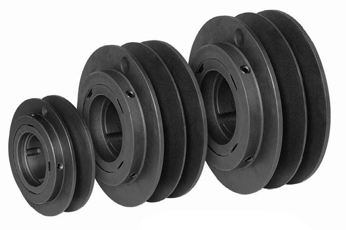
Pulleys provide rotation speeds of 800, 2000 and 3000 rpm
Before designing and assembling a wood lathe with your own hands, you should watch a video on making such equipment. Such a video can easily be found on specialized websites dedicated to the manufacture of woodworking equipment.
The use of an electric sharpener for the manufacture of the headstock is suitable in all respects - the axis of rotation is located high, in addition to this, the unit already has 4 washers made of hard alloy. Two washers are used to install replaceable disks of different diameters on the shaft of the electric grinder, which are designed to change the rotation speed. On the other side, a special faceplate is made from one of the washers to secure the blank.
To drive the shaft, pulleys of different diameters are used, providing rotation speeds of 800, 2000 and 3000 rpm. If possible, it is possible to make one combined pulley with seats of different diameters for the drive belt.
Manufacturing the bed, tailstock and stop
From an old hand-held electric drill, the chuck and the front part of the body are taken, from which the tailstock is made. When using a part from a hand-held electric drill as a tailstock, you need to choose a drill with a metal body.
To secure the unit, a stand is made, fixed to the machine bed, so that it is possible to move the unit along the longitudinal axis of the machine. The design of the cartridge allows significant longitudinal loads to be placed on it, which is a significant advantage when using it in the design of the device.
The bed is made from pieces of channel material. All elements of the frame are connected to each other using a welding machine. To install the electric sharpener, which performs the functions of the headstock, a platform made of thick plywood is fixed to the frame.
A stand is made to secure the lathe
The electric drive of the machine is installed on a special plate mounted on the table on which the lathe bed is installed. The plate is made in such a way that it can be moved along the direction of movement of the belt. This is necessary to adjust the rotation speed of the headstock shaft.
A support is fixed to the frame with the possibility of its smooth movement along and across the frame. It is made of two pipes of different diameters. A wing nut is used to secure this unit. A stop bar is fixed to the support, on which the cutters for the wood lathe are located during its operation.
Working tools - cutters for working on a wood turning unit can be made with your own hands, using tool steel plates for this purpose, or purchased ready-made in a specialized store. The cost of a set of cutters for working on a lathe ranges from 300 rubles to several thousand rubles. The cost of the set depends on the quality of the cutters and their quantity in the set.
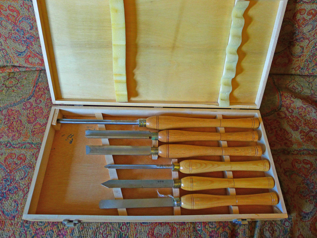
The cost of a set of cutters for working on a lathe ranges from 300 rubles to several thousand rubles
Basic rules for operating turning equipment
After making a wood lathe with your own hands, it is recommended to watch a video on how to safely and correctly work on such equipment. This will allow you to familiarize yourself not only with the rules of operation on this type of equipment, but also to study the safety rules when operating a turning unit.
General instructions for using turning equipment for wood processing include several points that require mandatory implementation. The main points to be fulfilled are the following:
- Selecting a workpiece for processing. The workpiece intended for processing must not have knots, cracks or other wood defects.
- Installation of the workpiece into the unit for turning. Installation and fastening of the workpiece in the unit is carried out using special fasteners located on the headstock shaft and on the rear panel.
- Selecting the optimal shaft rotation speed during workpiece processing. The number of revolutions is selected by rearranging the drive belt on drive pulleys having different seat sizes.
- Carrying out processing of a workpiece by using special cutters for this purpose. During processing, the actual dimensions of the part should be measured periodically. To work with this type of equipment and produce quality products, experience is required. The fact is that when using such equipment, one awkward movement with a cutter is enough to ruin the workpiece.
The optimal option for designing a reliable working unit is an integrated approach to the manufacture of each structural element. The frame of the unit should be made especially well. This element must provide a high degree of stability during equipment operation. The quality of functioning of the remaining equipment components also depends on the quality of the frame.
The disadvantage of this type of design is the high labor intensity when changing the number of spindle revolutions.
The optimal option for designing a reliable working unit is an integrated approach to the manufacture of each structural element
The choice of the optimal headstock shaft speed depends on the size of the workpiece used and the type of wood. To select the required rotation speed, it is recommended to use special tables depending on the rotation speed on the diameter of the workpiece and wood.
Our article is devoted to nostalgia for school labor training workshops. Many people know how to do wood turning, but not everyone can afford to buy and maintain equipment for this. Is it possible to assemble a machine with your own hands that meets technology and safety requirements? Let’s figure it out together.
What GOST says
The good news is that you don't have to reinvent the wheel. The entire assembly process and drawings of each machine module are described in TU3872-477-02077099-2002, and although this document is not publicly available, it can be obtained upon individual request. Although this is unlikely to be needed: the device of the machine is so primitive that you can easily navigate the intricacies of its manufacture even from images from school textbooks.

Another positive fact is that the STD-120M was apparently designed for on-site production, so you can either find almost all components for assembly on sale or make and modify it yourself. Naturally, if you have the opportunity to inexpensively purchase components for this machine or its younger brother TD-120, do so. Factory-produced parts are more reliable, easier to adjust, and the unified frame design allows you to assemble one machine from many donors.

Please also note that standardization of modules largely determines the safety of equipment operation. Basic principles industrial safety are announced in GOST 12.2.026.0-93, and the rules of electrical protection are set out in GOST R IEC 60204-1. Harmonize any part or machine module you manufacture with these standards.
Manufacturing of the bed
Instead of a cast iron frame, we offer a lighter welded structure. It consists of two pieces of 72-gauge angle steel, each 1250 mm long. There is a great temptation to make the bed larger to process more massive products, but remember that such changes require intervention in other components of the machine. Perhaps you should take the TT-10460 as a sample for a meter-long workpiece.

We place the corners on a flat horizontal plane with shelves facing each other. We insert calibrated inserts between them so that the frame guides are positioned strictly parallel with a distance of 45 mm. To fasten the guides, we use two corners, the same as on the frame, 190 mm each, which we place on the front and rear edges. Before welding parts, it is recommended to squeeze them with clamps so that the metal does not move when it cools.
The guides are fastened with another 190 mm jumper, in the bottom shelf of which there are cutouts for each corner. This part is installed to form a cell, the dimensions exactly corresponding to the landing pin of the headstock, in standard version this is 45x165 mm.

Such a frame can be attached in any way to a workbench or deck, but it is recommended to weld all fastening elements without compromising the integrity of the base. If a separate corner is allocated for the machine, weld pipe legs perpendicular to the corners of the frame and, for greater stability, make a small “brace” for them with a sledgehammer. Ultimately, the weight of the frame attached to the workbench should not be less than 60-70 kg.

Podruchnik
This element conditionally consists of two parts. For both, you need one type of workpiece - a 50 mm corner, inside of which another, 30 mm wide, is inserted. They are welded along the edges, in the end you should get two sections of 260 and 600 mm.

The short part is the adjustable base of the hand rest. One of the shelves is cut off, but not completely, leaving a 110 mm long section with an inclined cut. The other shelf is cut at a right angle 60 mm from the rear edge. You need to make a counter frame from a thick steel plate that will clamp the guide of the tool rest.

To make a guide with a clamp, take a regular inch pipe and make a longitudinal cut in it with a grinder. The resulting sleeve should be about 150 mm long; we insert it into a 25 mm corner, orienting the slot outward perpendicular to one of the shelves. We tighten the parts with a clamp and weld along the entire length closest to the shelf slot. We cover the workpiece with a second corner of the same length and attach it to the tube from the back side.

The guide is welded flat to the protruding flange of the adjustment rail on its inner side. For fixation, a screw with a long handle and a nut welded to the rail are used. On the reverse side, the strike plate is fastened with a cotter pin or even a welded rod.

The handrail is mounted on a 20 mm smooth reinforcement rod, which is located centrally on the outside of the corner blank. The rod fits tightly into the tube of the guide system, and when the screw is tightened, it is securely pressed on all sides. A long corner piece 600 mm long is welded to the rod with a slight inclination toward itself and a slightly “sharpened” leading edge.


Drive and transmission
The standard drive option is asynchronous three phase motor power up to 2 kW (usually 1.2 kW), connected to the headstock shaft by a V-belt drive on double-groove pulleys. The bed for fastening the engine can be located between the legs of the frame, or on an additional scaffold behind the headstock, which will complicate the assembly, but will make it more convenient to transfer the belt.

It is not always possible to use the engine at the required shaft speed, so reaching the final speed is achieved by adjusting the diameter of the pulleys. For example, if you have a blood pressure at 1480 rpm, then in order to reach the coveted 1100 and 2150 rpm, the diameters of the leading and driven streams must be in a ratio of 1:1.5 and 1.3:1.
When placing the engine, it is useful to provide the frame with a plate attached to the gate canopies. An engine installed using such a system will be in a suspended state all the time and will ensure that the belt is tightly pressed by its own weight. And if you equip the platform with a pedal, the speed can be changed even on the go.

There are no problems with the electrical part either. Switching is performed by a standard three-phase starting button with reverse; for such a low-power motor there is no need to install a starter. The only thing is turning on the brakes DC while holding down the stop button, for which you will need a powerful diode bridge (on KD203D) according to standard scheme inclusions.
Frequency controlled motor can be used as direct drive, which will eliminate the need to construct a headstock. To do this, you need to fix the engine on the transition platform, in the lower part of which there is a longitudinal mounting spike 45 mm wide as a standard means of adjustment for the STD120 frame.

Headstock
Looking ahead, we note that both the front and tailstock include parts that can only be made with access to a metal lathe. Otherwise, it makes sense to think about purchasing ready-made modules, or at least their cast consoles.
At the base of the headstock there are two bearing housings of types S, V or U, permanently mounted on an angle steel frame. Unfortunately, it is impossible to predict which sizes will be available, but in general, the height of the spindle axis above the bed should be at least 120 mm. Given that the diameter of the spindle shaft is about 25 mm, the most interesting would be the standard size of the bearing unit with a total height dimension of about 70 mm.

The shaft is machined from round carbon steel with a diameter of 40 mm with a tolerance of no more than 0.05 mm. There are two main variations of the shaft. The first is the simplest: the shaft pillar remains in the center, then descents are made to the landing diameter of the bearing units, then threads are cut at the ends. For axial fixation, four grooves are machined on the shaft for retaining rings.
 1 — seats for bearings; 2 — grooves for retaining rings
The second variation has an extension in the form of a skirt immediately behind the cartridge thread. It is designed to install a flanged thrust bearing mounted on the boss of the headstock base. This approach allows you to reduce bearing wear if massive parts are processed on the machine.
The base of the headstock is two pairs of corners or two channels turned towards each other. By moving the vertical shelves together, you can adjust the height of the base to the axial height of the existing bearing units. A 45 mm strip is welded to the base below, which acts as an adjustment groove. The order of assembly is important: first, bearings are pressed onto the spindle, then the shaft is mounted on a frame with a backing of adjusting steel plates.

Tailstock
Making a tailstock is much easier. It consists of four parts:
- The base is made from angle steel, 100mm high, using the same principle as for the headstock. Two 50 mm corners are bolted across the top; in their shelves in the center there are cutouts with squares 40 mm wide.
- The guide (external) thick-walled square tube is 40 mm wide, 150 mm long and has an internal clearance of 20x20 mm. In the rear part you need to install a plug 6-8 mm thick and with a hole in the center of 8 mm, it is secured with two screws through the walls of the tube.
- The inner tube, also known as the quill, is made from a 20 mm profile tube, preferably thick-walled and milled exactly to fit the guide clearance. An M14 nut is welded in the rear part of the quill; a metal rod, widened to 5 mm, is inserted and welded into the front part, widened to 5 mm to fit a double-row bearing.
- The drive screw has a thread for a nut in the quill (it is advisable to make it trapezoidal); in the rear part there is a transition to an 8 mm thread for attaching the flywheel.

The principle of operation and assembly diagram of the quill are quite obvious, but Special attention You need to pay attention to aligning the axes. The guide tube, fixed by welding in the cutouts of the corners, can rise higher or lower due to linings made of transformer steel. The headstock and tailstock must be absolutely aligned, the tolerance is only a couple of tenths.

As for the method of attachment to the frame, it is the same for both the headstocks and the tool rest. M14 or M16 studs are welded to the bottom of the headstocks, and a large plowshare bolt is inserted into the slot of the tool rest. The modules are tightened from below with nuts with rods welded to them like levers. For uniform, tight pressing from below, a 50 mm channel is placed as a counter strip.
A homemade lathe for woodworking is a very useful thing for a true craftsman’s home; with its help you can make a variety of useful or simply beautiful things
The summer before last I made a wood lathe. Some design flaws have come to light and I will be eliminating them next summer in the workshop (in a rebuilt barn at the dacha, by the way, look at which one, as well). Dimensions of the machine; length 800 mm, width 400 mm, height 350 mm. Allows you to sharpen workpieces with a diameter of up to 250 mm and a length of up to 200 mm (on a faceplate, i.e. without centering with a tailstock) and with centering with a tailstock up to 400 mm. General view photo 1.
A homemade wood lathe consists of:
- drive - electric motor from the pump
- headstock (old powerful electric sharpener with two sharpening stones)
- supports for cutters with adjustment and support for cutters
- tailstock from part of a powerful old drill
- frames made of metal profile.
In the manufacture of a lathe, ordinary metalworking tools were used:
- drill with drill bits
- files
- small angle grinder (grinder with cutting and cleaning discs)
- electric welding machine with 3 mm and 2 mm electrodes.
Purchased on the market a metal profile (channel) and an angle, some pipes of two diameters (so that one pipe fits into the other), a 40 mm strip and a 20 mm strip. only for the amount of 600 rubles. Photo 2. The necessary fasteners were found in the garage. I purchased a drive belt from some company separately (to fit the length).  The headstock from the sharpener met all the parameters - a high-mounted axis of rotation, protected thrust bearings on the axis, four alloy washers for fastening abrasive discs. Replaceable disks are attached to two washers on the left side to change the rotation speed, and on the right side there is a faceplate for installing the blank (also made from one of the washers)
  The photo also shows part of the drill (an old burnt Soviet one) - a chuck and a metal body. This is precisely the most unfinished component of the machine.
Disadvantages: the stand is rather weak, there is no lead screw for moving the headstock (I moved it with a lever and secured with a nut). The chuck itself is comfortable and allows forces along the chuck axis by default.  Photo 4 shows a bed with a support. It can move along the frame and across it, and is fixed with a wing nut. On the support there is a stand (pipe in a pipe) for adjusting the height of the stop bar for the cutters.
  To select the diameters of the pulleys (i.e., change the rotation speed of the workpiece), a graph (found on the Internet) was used - the dependence of the rotation speed on the diameter of the workpiece and the hardness of the wood. Two frequencies are selected that overlap each other. In addition, for some small jobs with hard wood, you can use a sharpener motor, i.e. with the drive turned off (removing the belt and turning off the motor). This way I can set three rotation speeds - 800, 2000, 3000 rpm. , practically covering my needs.
  In the photo we see a rubberized cartridge on the axis of the electric motor, which plays the role of a drive pulley, two driven pulleys (each made of two layers of ten-millimeter plywood) and a faceplate with holes for screws securing the workpiece. The faceplate is simply screwed onto the sharpener axis (i.e., the headstock) after installing the blank.
  To mount the motor, a platform is made of thick plywood, and the headstock sits on it (thereby increasing the possibility of turning a larger diameter). To adjust the belt tension, the motor stands on a small plate (no photo), which has the ability to move along the platform and be fixed on it. As a rule, professionals who have chosen this job or hobby make the equipment themselves - cutters different types. I bought ready-made and inexpensive ones for the first time - five cutters for 350 rubles each.
  Quite a lot of souvenirs were turned on this machine, which were distributed among friends and acquaintances - salt shakers, boxes, simple and segmented vases (from several types of wood in one product), cups, large decorative plates on the wall, sockets, etc. This is in the following articles.

