Let's try to make a voltage converter ourselves. High voltage and more Converter circuit 12 220 to 300 watts
Nowadays, everyone on the household or in general has easy access sometimes has several power supplies from a computer that are not needed, they just lie there, gathering dust and taking up valuable space. Or maybe they are completely burnt, but this does not matter, because you only need to take some elements from it. I once assembled a board for such a converter (). And I decided to make another one again, since there were radio components, and the printed circuit board had already been made once in excess. I used a new chip from a store, but sometimes they or similar analogues are installed in the ATX power supplies themselves.
Small size transformer - from a 250 watt unit. I decided to take extra transistors - 44N field-effect ones, also completely new.

I found an aluminum radiator, screwed the transistors through plugs and substrates, thoroughly coating everything with thermal paste.

The 12-220 voltage converter circuit started up immediately, power was supplied from a 12 volt 7 a/h battery, the terminals of which had about 13 volts when freshly charged. As a load (approximately it was intended for this power) - a 60-watt light bulb at 220 volts, it doesn’t glow at full intensity, but it’s still good.

The radiator was taken very generously - the thickness is 2 mm aluminum, it dissipates heat well. After half an hour of work under load field effect transistors only heated up to 40 degrees! Current consumption is approximately 2.7 amperes from the battery, stable operation without breakdowns or overheating, but the transformer is somewhat small and gets hot (though it can withstand and does not burn anything) the temperature of the transformer is about 5-60 degrees when operating at the same load, I don’t think it can pull more than 80 watts from such a converter or you will have to install active cooling in the form of a fan, because the transistors will withstand much greater loads and I am more than sure that with such a radiator they will last all 200 watts.

The 12-220 converter circuit is easy to repeat; when assembled exactly to the nominal value, both boards worked immediately.
Converter test video
A video of the circuit's operation clearly shows the current flowing in the circuit and the operation of a 60-watt lamp. By the way, the wires of the D832 multimeter at this current became quite warm in half an hour. From the improvements, if you install larger transformer, then expand the signet, otherwise a larger transformer will not fit in size, and even with a small one everything works out.

For fans of miniaturization, of course, this is good, but the distance from the transformer to the transistors turns out to be less than 1 cm in practice, and with their heat they slightly warm up the already warm transformer, it would be nice to take the keys a couple more centimeters and make a couple of holes in the board for flow-through ventilation air flow from bottom to top. The author of the material is Redmoon.
Hello. Today I will talk about a fairly powerful converter (inverter) with 12 volts DC at 220 volts alternating. The declared power of this converter is as much as 3000 W. I’ll try to show whether this is true or not in the review.
The review will also include disassembly, a detailed examination of all the internals, and testing.
I bought the subject for $55.38 + $19.57 shipping, total $74.95. Now it's a little more expensive.
For those interested, please...
Motivation:
Why did I need this inverter? The thing is, my car is parked in my yard. apartment building Without a garage and simply vacuuming it, I can’t. I tried to use a 12-volt car vacuum cleaner, but by and large it is a toy. So I decided to look towards such converters. My vacuum cleaner is 1500 watt, so I decided to take an inverter with 2 power reserves.Packaging and accessories:
The parcel arrived by EMS, but this did not save it from the “professional” actions of Russian Post employees. It feels like the parcel was not just thrown, but walked on. But the metal body of the inverter was almost not damaged.

 The package is the most ascetic: an inverter, 2 short cables, instructions in English and Chinese.
 Inverter:
The overall dimensions of the inverter are: 28x15x7 cm;Weight about 2 kg.
The inverter is made in an aluminum case, at one end of which there are power terminals for connecting 12 volts, as well as 2 fans. At the second end there is a socket for connecting a load, a power switch, 2 LEDs (green and red), and a USB socket. The green LED lights up during normal operation of the inverter, red when one of the protections is triggered. Also, along with the glow of the red LED, the inverter emits a rather loud and nasty squeak.
Protection is triggered in following cases:
- supply voltage output from the range 10-15V;
- inverter overheating;
- inverter overload.


Disassembly:
To disassemble the inverter housing, you need to unscrew 8 screws from the ends (4 from each) and remove top part housings. Block by block, the internal filling of the device can be represented as follows:
  Now I will describe it in words. At the inverter input there are 4 converters from 12 volts DC to 300 volts DC. All these 4 converters are connected in parallel. Each converter consists of 2 CMP1405 field-effect transistors, a step-up transformer and a full-wave rectifier using UF2004 diodes. The transistors are quite powerful (maximum drain current is 140 amperes), but the diodes are not so good. The diodes are only 2 ampere. But because in a diode bridge they work alternately, then in theory the maximum output current of each of the 4 converters is 4 amperes. Those. 16 amps with 4 converters. Those. the total output power is as much as 4800 W. It seems that there is also a reserve.
 The generator on the TL494 chip controls the operation of field-effect transistors of all converters
So, at the output of the 4 converters described above, we get 300 volts DC. To turn it into AC, another converter is used, from direct current to alternating current. It is also made on a TL494 microcircuit, to the output of which a bridge amplifier of 4 R6025ANZ field-effect transistors is connected

 The maximum drain current of these transistors is 25 amperes, and if we take into account that the transistors also operate alternately, then here too we have a very large power reserve.
 Well, the main parts of the “filling” have been disassembled, but nothing has been said about the USB connector. This connector can be used to charge various USB devices, but the 5 volts for it are generated by a conventional linear stabilizer 7805, which does not even have a heatsink, so I would not recommend connecting anything even more power-hungry to this socket.

Testing:
First, I’ll demonstrate the waveform at the inverter output This is the so-called “modified sine wave”. Most similar converters and various sources uninterruptible power supply The output produces alternating current with exactly this signal shape. It is much easier and cheaper to obtain such alternating current than a “pure sine wave”, and most modern electrical appliances. The exception is various loads with an inductive component, for example, asynchronous electric motors, transformers, etc. Switching power supplies and commutator motors work perfectly even on direct current, so they can “digest” a “modified sine wave” well.
 It's time to move on to the testing itself. To do this, the inverter was connected directly to the car battery, although through 4-meter extension wires, because The standard wires are very short and without “crocodiles” at the ends. A vacuum cleaner with a power of 1500 W was used as a load.
When checking operation with the engine turned off, the vacuum cleaner worked intermittently, because... less than 10 volts reached the inverter input (the rest fell on the wires), and the inverter was turned off by protection. With the engine running, the voltage at the inverter input was around 10.8 volts, the output was 207 volts, the vacuum cleaner worked perfectly.


Video review:
The video review includes unpacking, disassembling, and testing of the inverter under review.Result:
The inverter is fully operational and can be used for its intended purpose. I didn’t like the input wires, I will lengthen them and equip them with “crocodiles”. I'm planning to buy +36 Add to favorites I liked the review +56 +81Voltage for motorists, since in a car it may very often be necessary to obtain mains voltage. This converter can be used to power soldering irons, incandescent lamps, coffee makers and other devices that are powered from a 220 Volt network. The converter can also power active loads - a TV or DVD player, but it is worth noting that this is quite dangerous, since operating frequency The converter is quite different from the network 50 Hertz. But, as you know, these devices are equipped with switching power supplies, where mains voltage rectified by diodes. These diodes can rectify high frequency current, but I must note that not all pulse units can have such diodes, so it’s better not to risk it. Such a DC-AC voltage converter can be assembled in a couple of hours if you have the necessary components on hand. A scaled-down diagram is shown in the figure:
Transformer is the power component of such a converter. It is wound on a ring of ferrite, which was removed from a Chinese power supply unit for halogen lamps (power 60 watts).

The primary winding of the transformer was wound with 7 wires. To wind both windings, a wire with a diameter of 0.5-0.6 mm was used. The primary winding consists of 10 turns tapped from the middle, i.e. two equal halves of 5 turns each. The windings are stretched across the entire ring. After winding, it is advisable to insulate the windings and wind them with a step-up winding.

The secondary winding consists of 80 turns (the same wire was used as for winding the primary winding). The transistors were installed on heat sinks, but do not forget to insulate them using special gaskets and washers. This is done only when both transistors have a common heat sink.

The choke can be removed and the power connected directly. It consists of 7-10 turns of 1mm wire. The inductor can be wound on a ring made of powdered iron (such rings can easily be found in computer power supplies). The 12-220V inverter circuit does not require preliminary adjustment and works immediately.

The operation is quite stable, thanks to the additional driver, the chip does not heat up. The transistors heat up within normal limits, but I advise you to choose a larger heat sink for them.

The installation is carried out in a housing from an electronic transformer, which plays the role of a heat sink for field switches.
I propose a 12/220V voltage converter (inverter) circuit (power up to 500 Watt), powered by a 12V battery, which can be useful in a car and at home for lighting, to power a TV, a small refrigerator, etc. The circuit is assembled on two 155 series microcircuits and six transistors. The output stage uses field-effect transistors that have a very low on-resistance, which increases the efficiency of the converter and eliminates the need to install them on radiators that are too large.

Let's figure out how the circuit works: (see diagram and diagram). A generator is assembled on the D1 chip rectangular pulses, the repetition frequency of which is about 200 Hz - diagram “A”. From pin 8 of the microcircuit, pulses are sent further to frequency dividers assembled on elements D2.1 - D2.2 of microcircuit D2. As a result, at pin 6 of the D2 chip, the pulse repetition rate becomes half as much - 100 Hz - diagram "B", and at pin 8 the pulses become equal to the frequency of 50 Hz - diagram "C". Non-invertible 50 Hz pulses are removed from pin 9 - diagram “D”. An “OR” logic circuit is assembled on diodes VD1-VD2. As a result, the pulses taken from the pins of microcircuits D1 pin 8, D2 pin 6 form a pulse corresponding to diagram “E” at the cathodes of the diodes. The cascade on transistors V1 and V2 serves to increase the amplitude of the pulses necessary to fully open the field-effect transistors. Transistors V3 and V4 connected to outputs 8 and 9 of microcircuit D2 open alternately, thereby locking either one field-effect transistor V5 or another V6. As a result, control pulses are formed in such a way that there is a pause between them, which eliminates the possibility of through current flowing through the output transistors and significantly increases efficiency. Diagrams "F" and "G" show the generated control pulses for transistors V5 and V6.
A correctly assembled converter begins to work immediately after power is applied. When setting up, you should connect a frequency meter to the output of the device and set the frequency to 50-60 Hz by selecting resistor R1, and, if necessary, capacitor C1.
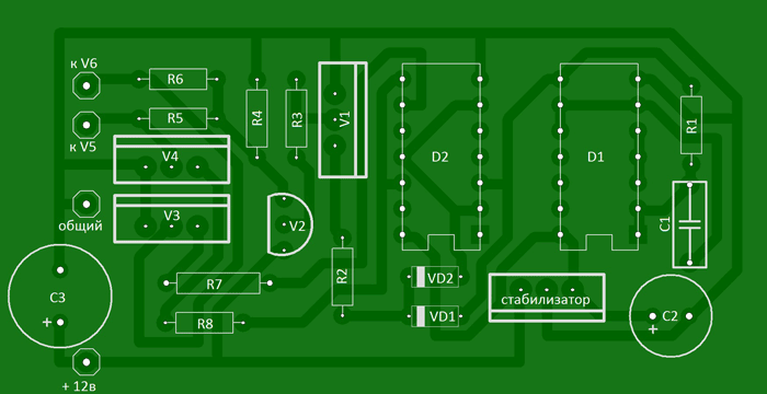
About details
Transistors KT315 with any letter index, KT209 can be replaced with KT361 with any letter index. We will replace the KA7805 voltage stabilizer with the domestic KR142EN5A. Any resistors with a power of 0.125...0.25 W. Almost any low-frequency diodes, for example KD105, IN4002. Capacitor C1 type K73-11, K10-17V with low capacity loss when warming up. The transformer was taken from an old tube black and white TV, for example: “Spring”, “Record”. The 220 volt winding remains, and the remaining windings are removed. Two windings are wound on top of this winding with PEL wire - 2.1 mm. For better symmetry, they should be wound simultaneously into two wires. When connecting the windings, take into account the phasing. Field-effect transistors are fixed through mica spacers to a common aluminum radiator with a surface area of at least 600 sq.cm.


List of radioelements
| Designation | Type | Denomination | Quantity | Note | Shop | My notepad |
|---|---|---|---|---|---|---|
| Linear regulator | UA7805 | 1 | KR142EN5A | To notepad | ||
| D1 | Valve | K155LA3 | 1 | To notepad | ||
| D2 | D-trigger | K155TM2 | 1 | To notepad | ||
| V1, V3, V4 | Bipolar transistor | KT315B | 3 | To notepad | ||
| V2 | Bipolar transistor | KT209A | 1 | KT361 | To notepad | |
| V5, V6 | MOSFET transistor | IRLR2905 | 2 | Through mica spacers | To notepad | |
| VD1, VD2 | Diode | KD522A | 2 | KD105, 1N4002, etc. | To notepad | |
| C1 | Capacitor | 2.2 µF | 1 | K73-11, K10-17V | To notepad | |
| C2 | 470 µF | 1 | To notepad | |||
| C3 | Electrolytic capacitor | 2200 µF | 1 | To notepad | ||
| R1 | Resistor | 680 Ohm | 1 | To notepad | ||
| R2 | Resistor | 7.5 kOhm | 1 | To notepad | ||
| R3, R5-R8 | Resistor |
Many radio amateurs are also car enthusiasts and love to relax with friends in nature, but they don’t want to give up the benefits of civilization at all. Therefore, they assemble a 12 220 voltage converter with their own hands, the circuit of which is shown in the figures below. In this article I will tell and show various designs of inverters that are used to obtain 220 Volt mains voltage from a car battery.

The device is built on a push-pull inverter with two powerful field-effect transistors. Any N-channel field-effect transistors with a current of 40 Amps or more are suitable for this design, I used inexpensive transistors IRFZ44/46/48, but if you need more power at the output, better use more powerful field-effect transistors.

We wind the transformer on a ferrite ring or an E50 armored core, or you can use any other one. The primary winding should be wound with a two-core wire with a cross-section of 0.8 mm - 15 turns. If you use an armor core with two sections on the frame, the primary winding is wound in one of the sections, and the secondary winding consists of 110-120 turns copper wire 0.3-0.4mm. At the output of the transformer we obtain an alternating voltage in the range of 190-260 Volts, rectangular pulses.
The 12 220 voltage converter whose circuit has been described can power various loads, power of which is no more than 100 watts
Output pulse shape - Rectangular
A transformer in a circuit with two primary windings of 7 Volts (each arm) and a mains winding of 220 Volts. Almost any transformers from uninterruptible power supplies are suitable, but with a power of 300 watts or more. The diameter of the primary winding wire is 2.5 mm.

Transistors IRFZ44, if missing, can be easily replaced with IRFZ40,46,48 and even more powerful ones - IRF3205, IRL3705. The transistors in the TIP41 (KT819) multivibrator circuit can be replaced with domestic KT805, KT815, KT817, etc.
Attention, the circuit does not have protection at the output and input from short circuit or overload, the keys will overheat or burn out.
Two versions of the printed circuit board design and a photo of the finished converter can be downloaded from the link above.
This converter is quite powerful and can be used to power a soldering iron, grinder, microwave oven and other devices. But do not forget that its operating frequency is not 50 Hertz.

The primary winding of the transformer is wound with 7 cores at once, with a wire with a diameter of 0.6 mm and contains 10 turns with a tap from the middle stretched across the entire ferrite ring. After winding, we insulate the winding and begin to wind the step-up winding, with the same wire, but already 80 turns.
It is advisable to install power transistors on heat sinks. If you assemble the converter circuit correctly, it should work immediately and does not require any configuration.
As with the previous design, the heart of the circuit is the TL494.

This is a ready-made push-pull pulse converter device, complete domestic analogue hers is 1114EU4. High-efficiency rectifier diodes and a C-filter are used at the output of the circuit.
In the converter I used a ferrite W-shaped core from the TPI TV transformer. All the original windings were unwound, because I re-wound the secondary winding 84 turns with 0.6 wire in enamel insulation, then a layer of insulation and move on to the primary winding: 4 turns obliquely from 8 0.6 wires, after winding the windings were ringed and divided in half, we got 2 windings of 4 turns in 4 wires, the beginning of one was connected to the end of the other, so we made a tap from the middle, and finally wound the feedback winding with five turns of PEL 0.3 wire.
The 12 220 voltage converter circuit that we examined includes a choke. You can make it yourself by winding it on a ferrite ring from a computer power supply with a diameter of 10 mm and 20 turns of PEL 2 wire.

There is also a drawing of a printed circuit board for a 12,220 volt voltage converter circuit:

And a few photos of the resulting 12-220 Volt converter:

Again, I liked the TL494 paired with mosfets (This is such a modern type of field-effect transistors), this time I borrowed the transformer from an old computer power supply. When laying out the board, I took into account its conclusions, so be careful when choosing your placement option.

To make the case, I used a 0.25L soda can, which I had successfully snatched up after a flight from Vladivostok, cut off the top ring with a sharp knife and cut out the middle of it, and glued a circle of fiberglass with holes for a switch and connector into it using epoxy.

To give the jar rigidity, I cut out plastic bottle a strip the width of our case, and coated it with epoxy glue, placed it in a jar, after the glue dried, the jar became quite rigid and with insulated walls, the bottom of the jar was left clean, for better thermal contact with the radiator of the transistors.

To complete the assembly, I soldered the wires to the cover and secured it with hot glue; this will allow, if the need arises, to disassemble the voltage converter by simply heating the cover with a hairdryer.
The design of the converter is designed to convert 12 volt voltage from the battery into 220 volt alternating voltage with a frequency of 50 Hz. The idea for the scheme was borrowed from November 1989.
The amateur radio design contains a master oscillator designed for a frequency of 100 Hz on the K561TM2 trigger, a frequency divider by 2 on the same chip, but on the second trigger, and a power amplifier using transistors loaded by a transformer.

Taking into account the output power of the voltage converter, transistors should be installed on radiators with a large cooling area.
The transformer can be rewound from an old network transformer TS-180. The mains winding can be used as a secondary winding, and then windings Ia and Ib are wound.
A voltage converter assembled from working components does not require adjustment, with the exception of the selection of capacitor C7 with a connected load.
If you need a printed circuit board drawing made in , click on the PCB drawing.
Signals from the PIC16F628A microcontroller through 470 Ohm resistances control the power transistors, forcing them to open one by one. The half-windings of a transformer with a power of 500-1000 VA are connected to the source circuits of field-effect transistors. There should be 10 volts on its secondary windings. If we take a wire with a cross-section of 3 mm2, then the output power will be about 500 W.

The whole design is very compact, so you can use a breadboard without etching the tracks. You can catch the archive with the microcontroller firmware at the green link just above
The 12-220 converter circuit is made on a generator that creates symmetrical pulses following out of phase and an output block implemented on field springs, to the load of which is connected a step-up transformer. Using elements DD1.1 and DD1.2, a multivibrator is assembled according to the classical scheme, generating pulses with a repetition frequency of 100 Hz.

To form symmetrical pulses traveling in antiphase, the circuit uses a D-trigger of the CD4013 microcircuit. It divides by two all impulses entering its input. If we have a signal going to the input with a frequency of 100 Hz, then the output of the trigger will be only 50 Hz.
Since field-effect transistors have an insulated gate, the active resistance between their channel and the gate tends to an infinitely large value. To protect the trigger outputs from overload, the circuit has two buffer elements DD1.3 and DD1.4, through which the pulses travel to the field-effect transistors.
A step-up transformer is included in the drain circuits of the transistors. To protect against self-induction, high-power zener diodes are connected to the drains. RF interference suppression is carried out by a filter on R4, C3.
The inductor winding L1 is made by hand on a ferrite ring with a diameter of 28mm. It is wound with PEL-2 0.6 mm wire in one layer. The most common network transformer is 220 volts, but with a power of at least 100 W and having two secondary windings of 9 V each.
To increase the efficiency of the voltage converter and prevent severe overheating, field-effect transistors with low resistance are used in the output stage of the inverter circuit.

On DD1.1 – DD1.3, C1, R1, a rectangular pulse generator with a pulse repetition rate of 200 Hz is made. Then the pulses arrive at a frequency divider built on elements DD2.1 - DD2.2. Therefore, at the output of the divider 6, the output of DD2.1, the frequency is reduced to 100Hz, and already at the 8th output of DD2.2. it is 50 Hz.
The signal from pin 8 of DD1 and pin 6 of DD2 goes to diodes VD1 and VD2. To fully open the field-effect transistors, it is necessary to increase the amplitude of the signal that passes from the diodes VD1 and VD2; for this, VT1 and VT2 are used in the voltage converter circuit. The field-effect output transistors are controlled through VT3 and VT4. If no errors were made during the assembly of the inverter, then it starts working immediately after power is applied. The only thing that is recommended to do is to select the value of resistance R1 so that the output is the usual 50 Hz. VT5 and VT6. When output Q1 (or Q2) goes low, transistors VT1 and VT3 (or VT2 and VT4) open, and the gate capacitances begin to discharge, and transistors VT5 and VT6 close.
The converter itself is assembled according to the classic push-pull circuit.
If the voltage at the output of the converter exceeds the set value, the voltage at resistor R12 will be higher than 2.5 V, and therefore the current through the DA3 stabilizer will increase sharply and a high level signal will appear at the FV input of the DA1 chip.

Its outputs Q1 and Q2 will switch to the zero state and field-effect transistors VT5 and VT6 will close, causing a decrease in the output voltage.
A current protection unit based on relay K1 has also been added to the voltage converter circuit. If the current flowing through the winding is higher than the set value, the contacts of the reed switch K1.1 will operate. The FC input of the DA1 chip will be high and its outputs will go low, causing transistors VT5 and VT6 to close and a sharp decrease in current consumption.
After this, DA1 will remain in a locked state. To start the converter, a voltage drop at the input IN DA1 will be required, which can be achieved either by turning off the power or by short-circuiting capacitance C1. To do this, you can introduce a non-latching button into the circuit, the contacts of which are soldered parallel to the capacitor.
Since the output voltage is a square wave, capacitor C8 is designed to smooth it. The HL1 LED is necessary to indicate the presence of output voltage.
The T1 transformer is made from TS-180; it can be found in the power supplies of old CRT televisions. All its secondary windings are removed, and the network voltage of 220 V is left. It serves as the output winding of the converter. Half-windings 1.1 and I.2 are made from PEV-2 wire 1.8, 35 turns each. The beginning of one winding is connected to the end of the other.
The relay is homemade. Its winding consists of 1-2 turns of insulated wire, rated for current up to 20...30 A. The wire is wound on the reed switch body with making contacts.

By selecting resistor R3, you can set the required frequency of the output voltage, and resistor R12 - the amplitude from 215...220 V.