Series connection of resistors. Parallel connection of resistors
Not a single operation in electronics or electrical engineering is complete without calculating resistance. In this case, only the section of the chain in which the mixed compound resistors. Engineers and physicists need to understand exactly how calculations occur in such schemes. In total, there are several types of connections that are used in circuits of varying complexity.
Serial connection
There are such methods of connecting resistors: serial, parallel and combined. At serial connection the end of the first resistor is connected to the beginning of the second, and part of it to the third. This is how they work with all components. That is, all components of the chain follow each other. One common electric current will pass through them in such a connection. For such schemes, physicists use a formula in which between points A and B there is only one path for charged electrons to flow.

The resistance to flowing electricity depends on the number of connected resistors. The more components, the higher it is. It is calculated using the formula: R total = R1+R2+…+Rn, where:
- R total is the sum of all resistances;
- R1 - first resistor;
- R2 - second component;
- Rn is the last component in the chain.
Parallel connection
Parallel connection implies connecting the beginning of the resistors to one point, and ends to the other. The components themselves are located at the same distance from each other, and their number is not limited. Electricity flows through each component separately, choosing one of several paths.
 Because there are multiple components and current paths in the circuit, the resistance is much lower than with a series connection. That is, the total amount of counteraction decreases in proportion to the increase in the number of components. The formula for determining the total amount of resistance to electricity is: 1/R total = 1/R1+1/R2+…+1/Rn.
In calculations, the total resistance should always be less than any of the components of the circuit. The way to calculate the sum of opposition for a circuit of two resistors is slightly different: 1/R total = (R1 x R2)/(R1+R2). If the components in the system have the same resistance values, then total number will be equal to half of one of the components.
Mixed option
In a mixed connection of resistances, a serial and parallel connection circuit is combined. In this case, several components are connected in one way, and others in another, but they are all included in one circuit. In physics, this connection method is called series-parallel.
To calculate the amount of resistance to electricity, the circuit must be divided into small sections in which the resistors are connected in the same way. Then calculations are carried out according to the algorithm:
- in a circuit with parallel connected components, calculate the equivalent resistance;
- after this, the opposition is calculated in the series-connected sections of the circuit;
- the visual illustration needs to be redrawn, usually a circuit with resistors connected in series is obtained;
- calculate the resistance in the new circuit using one of two formulas.

An example will help you better understand the calculation methods. If there are only five components in a circuit, they may be arranged differently. The beginning of the first resistor is connected to point A, the end to B. A separate circuit with a combined connection comes from it. The second and third components are on a serial line, the fourth component is parallel to them. The last resistor comes from the end point of this circuit - G.
At first calculate the sum of the resistance of the serial section of the internal circuit: R2+R3. After this, the circuit is redrawn so that the second and third components are connected into one. As a result, the internal circuit is connected in parallel. Now its opposition is calculated: (R2.3xR4)/(R2.3+R4). You can draw the resulting circuit a second time.
The circuit will have three resistors connected in series. Moreover, the average includes the parameters of the second, third and fourth components.
 Now you can find out the total amount of resistance. To do this, add up the resistance to electricity indicators of the first, fifth and other components. The formula will look like: R1+(R2.3xR4)/(R2.3+R4)+R5. You can immediately substitute all the component parameters into it.
In practice, serial and parallel connection methods are rarely used, because the circuits in devices are usually complex. Therefore, resistors in circuits are often connected in a combined way. Resistance in such cases is calculated step by step.
If you immediately display the numbers in general formula, you can make a mistake and get incorrect results. This may adversely affect the operation of the electrical appliance.
When solving problems, it is customary to transform the circuit so that it is as simple as possible. To do this, equivalent transformations are used. Equivalent are those transformations of a part of an electrical circuit circuit in which the currents and voltages in the non-transformed part remain unchanged.
There are four main types of conductor connections: series, parallel, mixed and bridge.
Serial connection
Serial connection- this is a connection in which the current strength throughout the entire circuit is the same. A striking example of a series connection is an old Christmas tree garland. There the light bulbs are connected in series, one after another. Now imagine one light bulb burns out, the circuit is broken and the rest of the light bulbs go out. The failure of one element leads to the shutdown of all the others; this is a significant disadvantage of a serial connection.
When connected in series, the resistances of the elements are summed up.

Parallel connection
Parallel connection- this is a connection in which the voltage at the ends of the circuit section is the same. Parallel connection is the most common, mainly because all the elements are under the same voltage, the current is distributed differently and when one of the elements exits, all the others continue to work.

In a parallel connection, the equivalent resistance is found as:
In the case of two parallel connected resistors 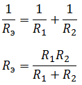
In the case of three resistors connected in parallel:


Mixed compound
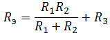
Mixed compound– a connection, which is a collection of serial and parallel connections. To find the equivalent resistance, you need to “collapse” the circuit by alternately transforming parallel and serial sections of the circuit.

First, let's find the equivalent resistance for the parallel section of the circuit, and then add to it the remaining resistance R 3 . It should be understood that after the conversion, the equivalent resistance R 1 R 2 and resistor R 3 are connected in series.
So, that leaves the most interesting and most complex connection of conductors.
Bridge circuit
The bridge connection diagram is shown in the figure below.

In order to collapse the bridge circuit, one of the bridge triangles is replaced with an equivalent star.

And find the resistances R 1, R 2 and R 3.
In electrical circuits, elements can be connected in various ways, including serial and parallel connections.
Serial connection
With this connection, the conductors are connected to each other in series, that is, the beginning of one conductor will be connected to the end of the other. The main feature of this connection is that all conductors belong to one wire, there are no branches. The same electric current will flow through each of the conductors. But the total voltage on the conductors will be equal to the combined voltages on each of them.
Consider a number of resistors connected in series. Since there are no branches, the amount of charge passing through one conductor will be equal to the amount of charge passing through the other conductor. The current strength on all conductors will be the same. This is the main feature of this connection.
This connection can be viewed differently. All resistors can be replaced with one equivalent resistor.
The current across the equivalent resistor will be the same as the total current flowing through all resistors. The equivalent total voltage will be the sum of the voltages across each resistor. This is the potential difference across the resistor.
If you use these rules and Ohm's law, which applies to each resistor, you can prove that the resistance of the equivalent common resistor will be equal to the sum of the resistances. The consequence of the first two rules will be the third rule.
Application
A serial connection is used when you need to purposefully turn on or off a device; the switch is connected to it in a series circuit. For example, an electric bell will only ring when it is connected in series with a source and a button. According to the first rule, if there is no electric current on at least one of the conductors, then there will be no electric current on the other conductors. And vice versa, if there is current on at least one conductor, then it will be on all other conductors. A pocket flashlight also works, which has a button, a battery and a light bulb. All these elements must be connected in series, since the flashlight needs to shine when the button is pressed.
Sometimes a serial connection does not achieve the desired goals. For example, in an apartment where there are many chandeliers, light bulbs and other devices, you should not connect all the lamps and devices in series, since you never need to turn on the lights in each of the rooms of the apartment at the same time. For this purpose, serial and parallel connections are considered separately, and a parallel type of circuit is used to connect lighting fixtures in the apartment.
Parallel connection
In this type of circuit, all conductors are connected in parallel to each other. All the beginnings of the conductors are connected to one point, and all the ends are also connected together. Let's consider a number of homogeneous conductors (resistors) connected in a parallel circuit.

This type of connection is branched. Each branch contains one resistor. Electricity, having reached the branching point, is divided into each resistor, and will be equal to the sum of the currents at all resistances. The voltage across all elements connected in parallel is the same.
All resistors can be replaced with one equivalent resistor. If you use Ohm's law, you can get an expression for resistance. If, with a series connection, the resistances were added, then with a parallel connection, the inverse values of them will be added, as written in the formula above.
Application
If we consider connections in domestic conditions, then in an apartment lighting lamps and chandeliers should be connected in parallel. If we connect them in series, then when one light bulb turns on, we turn on all the others. With a parallel connection, we can, by adding the corresponding switch to each of the branches, turn on the corresponding light bulb as desired. In this case, turning on one lamp in this way does not affect the other lamps.
All electrical household devices in the apartment are connected in parallel to a network with a voltage of 220 V, and connected to the distribution panel. In other words, parallel connection is used when it is necessary to connect electrical devices independently of each other. Serial and parallel connections have their own characteristics. There are also mixed compounds.
Current work
The series and parallel connections discussed earlier were valid for voltage, resistance and current values being the fundamental ones. The work of the current is determined by the formula:
A = I x U x t, Where A– current work, t– flow time along the conductor.
To determine operation with a series connection circuit, it is necessary to replace the voltage in the original expression. We get:
A=I x (U1 + U2) x t
We open the brackets and find that in the entire diagram, the work is determined by the amount at each load.
We also consider a parallel connection circuit. We just change not the voltage, but the current. The result is:
A = A1+A2
Current power
When considering the formula for the power of a circuit section, it is again necessary to use the formula:
P=U x I
After similar reasoning, the result is that series and parallel connections can be determined by the following power formula:
P=P1 + P2
In other words, for any circuit, the total power is equal to the sum of all powers in the circuit. This can explain that it is not recommended to turn on several powerful electrical devices in an apartment at once, since the wiring may not withstand such power.
The influence of the connection diagram on the New Year's garland
After one lamp in a garland burns out, you can determine the type of connection diagram. If the circuit is sequential, then not a single light bulb will light up, since a burnt out light bulb breaks the common circuit. To find out which light bulb has burned out, you need to check everything. Next, replace the faulty lamp, the garland will function.

When using a parallel connection circuit, the garland will continue to work even if one or more lamps have burned out, since the circuit is not completely broken, but only one small parallel section. To restore such a garland, it is enough to see which lamps are not lit and replace them.
Series and parallel connection for capacitors

With a series circuit, the following picture arises: charges from the positive pole of the power source go only to the outer plates of the outer capacitors. , located between them, transfer charge along the circuit. This explains the appearance of equal charges with different signs on all plates. Based on this, the charge of any capacitor connected in a series circuit can be expressed by the following formula:
q total = q1 = q2 = q3
To determine the voltage on any capacitor, you need the formula:
Where C is capacity. The total voltage is expressed by the same law that is suitable for resistances. Therefore, we obtain the capacity formula:
С= q/(U1 + U2 + U3)
To make this formula simpler, you can reverse the fractions and replace the ratio of the potential difference to the charge on the capacitor. As a result we get:
1/C= 1/C1 + 1/C2 + 1/C3
The parallel connection of capacitors is calculated a little differently.

The total charge is calculated as the sum of all charges accumulated on the plates of all capacitors. And the voltage value is also calculated by general laws. In this regard, the formula for the total capacitance in a parallel connection circuit looks like this:
С= (q1 + q2 + q3)/U
This value is calculated as the sum of each device in the circuit:
C=C1 + C2 + C3
Mixed connection of conductors
IN electrical diagram sections of the circuit can have both serial and parallel connections, intertwined with each other. But all the laws discussed above for individual species connections are still valid and are used in stages.

First you need to mentally decompose the diagram into separate parts. For a better representation, it is drawn on paper. Let's look at our example using the diagram shown above.
It is most convenient to depict it starting from the points B And IN. They are placed at some distance from each other and from the edge of the sheet of paper. From the left side to the point B one wire is connected, and two wires go off to the right. Dot IN on the contrary, it has two branches on the left, and one wire goes off after the point.
Next you need to depict the space between the points. Along the upper conductor there are 3 resistances with conventional values 2, 3, 4. From below there will be a current with index 5. The first 3 resistances are connected in series in the circuit, and the fifth resistor is connected in parallel.
The remaining two resistances (the first and sixth) are connected in series with the section we are considering B-C. Therefore, we supplement the diagram with 2 rectangles on the sides of the selected points.
Now we use the formula for calculating resistance:
- The first formula for the series connection.
- Next, for the parallel circuit.
- And finally for the sequential circuit.
In a similar way, you can decompose any complex circuit, including connections not only of conductors in the form of resistances, but also of capacitors. To learn how to calculate using different types schemes, you need to practice in practice by completing several tasks.
Content:The flow of current in an electrical circuit is carried out through conductors, in the direction from the source to the consumers. Most of these schemes use copper wires And electrical receivers in a given quantity, having different resistance. Depending on the tasks performed, electrical circuits use serial and parallel connections of conductors. In some cases, both types of connections can be used, then this option will be called mixed. Each circuit has its own characteristics and differences, so they must be taken into account in advance when designing circuits, repairing and servicing electrical equipment.
Series connection of conductors
In electrical engineering great importance has a serial and parallel connection of conductors in an electrical circuit. Among them, a series connection scheme of conductors is often used, which assumes the same connection of consumers. In this case, inclusion in the circuit is performed one after another in order of priority. That is, the beginning of one consumer is connected to the end of another using wires, without any branches.
The properties of such an electrical circuit can be considered using the example of sections of a circuit with two loads. The current, voltage and resistance on each of them should be designated respectively as I1, U1, R1 and I2, U2, R2. As a result, relations were obtained that express the relationship between quantities as follows: I = I1 = I2, U = U1 + U2, R = R1 + R2. The data obtained are confirmed in practice by taking measurements with an ammeter and a voltmeter of the corresponding sections.
Thus, the series connection of conductors has the following individual features:
- The current strength in all parts of the circuit will be the same.
- The total voltage of the circuit is the sum of the voltages in each section.
- The total resistance includes the resistance of each individual conductor.
These ratios are suitable for any number of conductors connected in series. The total resistance value is always higher than the resistance of any individual conductor. This is due to an increase in their total length when connected in series, which also leads to an increase in resistance.

If you connect identical elements in series n, you get R = n x R1, where R is the total resistance, R1 is the resistance of one element, and n is the number of elements. Voltage U, on the contrary, is divided into equal parts, each of which is n times less than the total value. For example, if 10 lamps of the same power are connected in series to a network with a voltage of 220 volts, then the voltage in any of them will be: U1 = U/10 = 22 volts.
Conductors connected in series have a characteristic distinctive feature. If at least one of them fails during operation, the current flow stops in the entire circuit. Most a shining example is when one burnt-out light bulb in a series circuit leads to failure of the entire system. To identify a burnt out light bulb, you will need to check the entire garland.
Parallel connection of conductors
IN electrical networks conductors can be connected different ways: series, parallel and combined. Among them, a parallel connection is an option when the conductors at the starting and ending points are connected to each other. Thus, the beginnings and ends of the loads are connected together, and the loads themselves are located parallel to each other. An electrical circuit may contain two, three or more conductors connected in parallel.

If we consider a series and parallel connection, the current strength in the latter can be studied using the following circuit. Take two incandescent lamps that have the same resistance and are connected in parallel. For control, each light bulb is connected to its own. In addition, another ammeter is used to monitor the total current in the circuit. The test circuit is supplemented by a power source and a key.
After closing the key, you need to monitor the readings of the measuring instruments. The ammeter on lamp No. 1 will show the current I1, and on lamp No. 2 the current I2. The general ammeter shows the current value, equal to the sum currents of individual, parallel-connected circuits: I = I1 + I2. Unlike a series connection, if one of the bulbs burns out, the other will function normally. Therefore, parallel connection of devices is used in home electrical networks.
Using the same circuit, you can set the value of the equivalent resistance. For this purpose, a voltmeter is added to the electrical circuit. This allows you to measure the voltage in a parallel connection, while the current remains the same. There are also crossing points for the conductors connecting both lamps.

As a result of measurements, the total voltage for a parallel connection will be: U = U1 = U2. After this, you can calculate the equivalent resistance, which conditionally replaces all the elements in a given circuit. With a parallel connection, in accordance with Ohm's law I = U/R, the following formula is obtained: U/R = U1/R1 + U2/R2, in which R is the equivalent resistance, R1 and R2 are the resistances of both bulbs, U = U1 = U2 is the voltage value shown by the voltmeter.
One should also take into account the fact that the currents in each circuit add up to the total current strength of the entire circuit. In its final form, the formula reflecting the equivalent resistance will look like this: 1/R = 1/R1 + 1/R2. As the number of elements in such chains increases, the number of terms in the formula also increases. The difference in basic parameters distinguishes current sources from each other, allowing them to be used in various electrical circuits.
A parallel connection of conductors is characterized by a fairly low equivalent resistance value, so the current strength will be relatively high. This factor should be taken into account when a large number of electrical appliances are plugged into sockets. In this case, the current increases significantly, leading to overheating of cable lines and subsequent fires.
Laws of series and parallel connection of conductors
These laws concerning both types of conductor connections have been partially discussed earlier.

For a clearer understanding and perception in a practical sense, series and parallel connection of conductors, formulas should be considered in a certain sequence:
- A series connection assumes the same current in each conductor: I = I1 = I2.
- The parallel and series connection of conductors is explained in each case differently. For example, with a series connection, the voltages on all conductors will be equal to each other: U1 = IR1, U2 = IR2. In addition, with a series connection, the voltage is the sum of the voltages of each conductor: U = U1 + U2 = I(R1 + R2) = IR.
- The total resistance of a circuit in a series connection consists of the sum of the resistances of all individual conductors, regardless of their number.
- With a parallel connection, the voltage of the entire circuit is equal to the voltage on each of the conductors: U1 = U2 = U.
- The total current measured in the entire circuit is equal to the sum of the currents flowing through all conductors connected in parallel: I = I1 + I2.
In order to more effectively design electrical networks, you need to have a good knowledge of the series and parallel connection of conductors and its laws, finding the most rational practical application for them.
Mixed connection of conductors
In electrical networks, serial parallel and mixed connection of conductors is usually used, intended for specific conditions operation. However, most often preference is given to the third option, which is a set of combinations consisting of various types of compounds.

Such mixed schemes Serial and parallel connections of conductors are actively used, the pros and cons of which must be taken into account when designing electrical networks. These connections consist not only of individual resistors, but also rather complex sections that include many elements.
The mixed connection is calculated according to the known properties of series and parallel connections. The calculation method consists of breaking the circuit down into simpler components, which are calculated separately and then summed up with each other.
When several power receivers are simultaneously connected to the same network, these receivers can easily be considered simply as elements of a single circuit, each of which has its own resistance.
In some cases, this approach turns out to be quite acceptable: incandescent lamps, electric heaters, etc. can be perceived as resistors. That is, the devices can be replaced with their resistances, and it is easy to calculate the circuit parameters.
The method of connecting power receivers can be one of the following: serial, parallel or mixed type of connection.
Serial connection

When several receivers (resistors) are connected in a series circuit, that is, the second terminal of the first is connected to the first terminal of the second, the second terminal of the second is connected to the first terminal of the third, the second terminal of the third is connected to the first terminal of the fourth, etc., then when such a circuit is connected to power source, a current I of the same magnitude will flow through all elements of the circuit. This idea is illustrated by the following figure.

Having replaced the devices with their resistances, we convert the drawing into a circuit, then resistances R1 to R4, connected in series, will each take on certain voltages, which in total will give the value of the EMF at the terminals of the power source. For simplicity, hereinafter we will depict the source in the form of a galvanic element.
Having expressed the voltage drops through current and through resistance, we obtain an expression for the equivalent resistance of a series circuit of receivers: the total resistance of a series connection of resistors is always equal to the algebraic sum of all resistances that make up this circuit. And since the voltages on each section of the circuit can be found from Ohm’s law (U = I*R, U1 = I*R1, U2 = I*R2, etc.) and E = U, then for our circuit we get:
The voltage across the power supply terminals is equal to the sum of the voltage drops across each of the series-connected receivers that make up the circuit.
Since the current flows through the entire circuit of the same value, it is fair to say that the voltages on series-connected receivers (resistors) are related to each other in proportion to the resistances. And the higher the resistance, the higher the voltage applied to the receiver will be.
For a series connection of n resistors with the same resistance Rk, the equivalent total resistance of the entire circuit will be n times greater than each of these resistances: R = n*Rk. Accordingly, the voltages applied to each of the resistors in the circuit will be equal to each other, and will be n times less than the voltage applied to the entire circuit: Uk = U/n.

The series connection of power receivers is characterized by the following properties: if you change the resistance of one of the receivers in the circuit, the voltages at the remaining receivers in the circuit will change; if one of the receivers breaks, the current will stop in the entire circuit, in all other receivers.
Due to these features, serial connection is rare, and it is used only where the network voltage is higher than the rated voltage of the receivers, in the absence of alternatives.
For example, with a voltage of 220 volts you can power two series-connected lamps of equal power, each of which is designed for a voltage of 110 volts. If these lamps have different rated power at the same rated supply voltage, then one of them will be overloaded and most likely will burn out instantly.
Parallel connection

Parallel connection of receivers involves connecting each of them between a pair of points in an electrical circuit so that they form parallel branches, each of which is powered by source voltage. For clarity, let’s again replace their receivers electrical resistances to obtain a diagram that is convenient for calculating parameters.

As already mentioned, in the case of a parallel connection, each of the resistors experiences the same voltage. And in accordance with Ohm’s law we have: I1=U/R1, I2=U/R2, I3=U/R3.
Here I is the source current. Kirchhoff's first law for a given circuit allows us to write down an expression for the current in its unbranched part: I = I1+I2+I3.
Hence, the total resistance for parallel connection of circuit elements can be found from the formula:
The reciprocal of resistance is called conductivity G, and the formula for the conductivity of a circuit consisting of several parallel-connected elements can also be written: G = G1 + G2 + G3. The conductivity of a circuit in the case of a parallel connection of the resistors forming it is equal to the algebraic sum of the conductivities of these resistors. Consequently, when parallel receivers (resistors) are added to the circuit, the total resistance of the circuit will decrease, and the total conductivity will correspondingly increase.
Currents in a circuit consisting of parallel-connected receivers are distributed between them in direct proportion to their conductivities, that is, inversely proportional to their resistances. Here we can give an analogy from hydraulics, where the flow of water is distributed through pipes in accordance with their cross-sections, then a larger cross-section is similar to less resistance, that is, greater conductivity.
If a circuit consists of several (n) identical resistors connected in parallel, then the total resistance of the circuit will be n times lower than the resistance of one of the resistors, and the current through each of the resistors will be n times less than the total current: R = R1/ n; I1 = I/n.
A circuit consisting of parallel-connected receivers connected to a power source is characterized in that each of the receivers is energized by the power source.
For ideal source electricity, the following statement is true: when resistors are connected or disconnected parallel to the source, the currents in the remaining connected resistors will not change, that is, if one or more receivers in the parallel circuit fail, the rest will continue to operate in the same mode.
Due to these features, a parallel connection has a significant advantage over a serial connection, and for this reason it is the parallel connection that is most common in electrical networks. For example, all electrical appliances in our homes are designed for parallel connection to the household network, and if you turn off one, it will not harm the rest at all.

Comparison of series and parallel circuits
By mixed connection of receivers we mean such a connection when part or several of them are connected to each other in series, and the other part or several are connected in parallel. In this case, the entire chain can be formed from different connections of such parts with each other. For example, consider the diagram:

Three series-connected resistors are connected to the power source, two more are connected in parallel to one of them, and the third is connected in parallel to the entire circuit. To find the total resistance of the circuit, they go through successive transformations: a complex circuit is sequentially reduced to a simple form, sequentially calculating the resistance of each link, and so the total equivalent resistance is found.

For our example. First, find the total resistance of two resistors R4 and R5 connected in series, then the resistance of their parallel connection with R2, then add R1 and R3 to the resulting value, and then calculate the resistance value of the entire circuit, including the parallel branch R6.
Various methods of connecting power receivers are used in practice for various purposes in order to solve specific problems. For example, a mixed connection can be found in smooth charging circuits in powerful power supplies, where the load (capacitors after the diode bridge) first receives power in series through a resistor, then the resistor is shunted by relay contacts, and the load is connected to the diode bridge in parallel.
Andrey Povny