DIY laboratory power supply. DIY power supply DIY 9v 1a power supply
The master whose device was described in the first part, having set out to make a power supply with regulation, did not complicate things for himself and simply used boards that were lying idle. The second option involves the use of an even more common material - an adjustment has been added to the usual block, perhaps this is a very promising solution in terms of simplicity, given that the necessary characteristics will not be lost and even the most experienced radio amateur can implement the idea with his own hands. As a bonus, there are two more options for very simple schemes with all the detailed explanations for beginners. So, there are 4 ways for you to choose from.
We'll tell you how to make an adjustable power supply from an unnecessary computer board. The master took the computer board and cut out the block that powers the RAM.
This is what he looks like.
Let's decide which parts need to be taken and which ones not, in order to cut off what is needed so that the board has all the components of the power supply. Typically, a pulse unit for supplying current to a computer consists of a microcircuit, a PWM controller, key transistors, an output inductor and an output capacitor, and an input capacitor. For some reason, the board also has an input choke. He left him too. Key transistors - maybe two, three. There is a seat for 3 transistors, but it is not used in the circuit.
The PWM controller chip itself may look like this. Here she is under a magnifying glass.

It may look like a square with small pins on all sides. This is a typical PWM controller on a laptop board.

This is what a switching power supply looks like on a video card.

The power supply for the processor looks exactly the same. We see a PWM controller and several processor power channels. 3 transistors in this case. Choke and capacitor. This is one channel.
Three transistors, a choke, a capacitor - the second channel. Channel 3. And two more channels for other purposes.
You know what a PWM controller looks like, look at its markings under a magnifying glass, look for a datasheet on the Internet, download the pdf file and look at the diagram so as not to confuse anything.
In the diagram we see a PWM controller, but the pins are marked and numbered along the edges.

Transistors are designated. This is the throttle. This is an output capacitor and an input capacitor. The input voltage ranges from 1.5 to 19 volts, but the supply voltage to the PWM controller should be from 5 volts to 12 volts. That is, it may turn out that a separate power source is required to power the PWM controller. All the wiring, resistors and capacitors, don’t be alarmed. You don't need to know this. Everything is on the board; you do not assemble a PWM controller, but use a ready-made one. You only need to know 2 resistors - they set the output voltage.
Resistor divider. Its whole point is to reduce the signal from the output to about 1 volt and apply feedback to the input of the PWM controller. In short, by changing the value of the resistors, we can regulate the output voltage. In the case shown, instead of a feedback resistor, the master installed a 10 kilo-ohm tuning resistor. This was sufficient to regulate the output voltage from 1 volt to approximately 12 volts. Unfortunately, this is not possible on all PWM controllers. For example, on PWM controllers of processors and video cards, in order to be able to adjust the voltage, the possibility of overclocking, the output voltage is supplied by software via a multi-channel bus. The only way to change the output voltage of such a PWM controller is by using jumpers.

So, knowing what a PWM controller looks like and the elements that are needed, we can already cut out the power supply. But this must be done carefully, since there are tracks around the PWM controller that may be needed. For example, you can see that the track goes from the base of the transistor to the PWM controller. It was difficult to save it; I had to carefully cut out the board.
Using the tester in dial mode and focusing on the diagram, I soldered the wires. Also using the tester, I found pin 6 of the PWM controller and the feedback resistors rang from it. The resistor was located in the rfb, it was removed and instead of it, a 10 kilo-ohm tuning resistor was soldered from the output to regulate the output voltage; I also found out by calling that the power supply of the PWM controller is directly connected to the input power line. This means that you cannot supply more than 12 volts to the input, so as not to burn out the PWM controller.
Let's see what the power supply looks like in operation
I soldered the input voltage plug, voltage indicator and output wires. We connect an external 12 volt power supply. The indicator lights up. It was already set to 9.2 volts. Let's try to adjust the power supply with a screwdriver.

It's time to check out what the power supply is capable of. I took a wooden block and a homemade wirewound resistor made from nichrome wire. Its resistance is low and, together with the tester probes, is 1.7 Ohms. We turn the multimeter into ammeter mode and connect it in series with the resistor. See what happens - the resistor heats up to red, the output voltage remains virtually unchanged, and the current is about 4 amperes.

The master had already made similar power supplies before. One is cut out with your own hands from a laptop board.

This is the so-called standby voltage. Two sources of 3.3 volts and 5 volts. I made a case for it on a 3D printer. You can also look at the article where I made a similar adjustable power supply, also cut from a laptop board (https://electro-repair.livejournal.com/3645.html). This is also a PWM power controller for RAM.
How to make a regulating power supply from a regular printer
We will talk about the power supply for a Canon inkjet printer. Many people have them idle. This is essentially a separate device, held in the printer by a latch.
Its characteristics: 24 volts, 0.7 amperes.

I needed a power supply for a homemade drill. It's just right in terms of power. But there is one caveat - if you connect it like this, the output will only get 7 volts. Triple output, connector and we get only 7 volts. How to get 24 volts?
How to get 24 volts without disassembling the unit?
Well, the simplest one is to close the plus with the middle output and we get 24 volts.
Let's try to do it. We connect the power supply to the 220 network. We take the device and try to measure it. Let's connect and see 7 volts at the output.
Its central connector is not used. If we take it and connect it to two at the same time, the voltage is 24 volts. This is the easiest way to ensure that this power supply produces 24 volts without disassembling it.
A homemade regulator is needed so that the voltage can be adjusted within certain limits. From 10 volts to maximum. It's easy to do. What is needed for this? First, open the power supply itself. It is usually glued. How to open it without damaging the case. There is no need to pick or pry anything. We take a piece of wood that is heavier or have a rubber mallet. Place it on a hard surface and tap along the seam. The glue is coming off. Then they tapped thoroughly on all sides. Miraculously, the glue comes off and everything opens up. Inside we see the power supply.

We'll get the payment. Such power supplies can be easily converted to the desired voltage and can also be made adjustable. On the reverse side, if we turn it over, there is an adjustable zener diode tl431. On the other hand, we will see the middle contact goes to the base of transistor q51.


If we apply voltage, then this transistor opens and 2.5 volts appears at the resistive divider, which is necessary for the zener diode to operate. And 24 volts appears at the output. This is the simplest option. Another way to start it is to throw out transistor q51 and put a jumper instead of resistor r 57 and that’s it. When we turn it on, the output is always 24 volts continuously.
How to make the adjustment?
You can change the voltage, make it 12 volts. But in particular, the master does not need this. You need to make it adjustable. How to do it? We throw away this transistor and replace the 57 by 38 kilo-ohm resistor with an adjustable one. There is an old Soviet one with 3.3 kilo-ohms. You can put from 4.7 to 10, which is what it is. Only the minimum voltage to which it can lower it depends on this resistor. 3.3 is very low and not necessary. The engines are planned to be supplied at 24 volts. And just from 10 volts to 24 is normal. If you need a different voltage, you can use a high-resistance tuning resistor.
Let's get started, let's solder. Take a soldering iron and hair dryer. I removed the transistor and resistor.

We soldered the variable resistor and will try to turn it on. We applied 220 volts, we see 7 volts on our device and begin to rotate the variable resistor. The voltage has risen to 24 volts and we rotate it smoothly and smoothly, it drops - 17-15-14, that is, it decreases to 7 volts. In particular, it is installed on 3.3 rooms. And our rework turned out to be quite successful. That is, for purposes from 7 to 24 volts, voltage regulation is quite acceptable.

This option worked out. I installed a variable resistor. The handle turns out to be an adjustable power supply - quite convenient.
Video of the channel “Technician”.
Such power supplies are easy to find in China. I came across an interesting store that sells used power supplies from various printers, laptops and netbooks. They disassemble and sell the boards themselves, fully functional for different voltages and currents. The biggest plus is that they disassemble branded equipment and all power supplies are of high quality, with good parts, all have filters.
The photos are of different power supplies, they cost pennies, practically a freebie.
Simple block with adjustment
A simple version of a homemade device for powering devices with regulation. The scheme is popular, it is widespread on the Internet and has shown its effectiveness. But there are also limitations, which are shown in the video along with all the instructions for making a regulated power supply.


Homemade regulated unit on one transistor
What is the simplest regulated power supply you can make yourself? This can be done on the lm317 chip. It almost represents a power supply itself. It can be used to make both a voltage- and flow-regulated power supply. This video tutorial shows a device with voltage regulation. The master found a simple scheme. Input voltage maximum 40 volts. Output from 1.2 to 37 volts. Maximum output current 1.5 amperes. 
Without a heat sink, without a radiator, the maximum power can be only 1 watt. And with a radiator 10 watts. List of radio components. 
Let's start assembling 


Let's connect an electronic load to the output of the device. Let's see how well it holds current. We set it to minimum. 7.7 volts, 30 milliamps.
 Everything is regulated. Let's set it to 3 volts and add current. We’ll only set larger restrictions on the power supply. We move the toggle switch to the upper position. Now it's 0.5 ampere. The microcircuit began to warm up. There is nothing to do without a heat sink. I found some kind of plate, not for long, but enough. Let's try again. There is a drawdown. But the block works. Voltage adjustment is in progress. We can insert a test into this scheme.
Radioblogful video. Soldering video blog.
Adjustable voltage source from 5 to 12 volts
Continuing with our guide to converting an ATX power supply into a desktop power supply, one very nice addition to this is the LM317T positive voltage regulator.
The LM317T is an adjustable 3-pin positive voltage regulator capable of supplying a variety of DC outputs other than a +5 or +12V DC source, or as an AC output voltage from a few volts to some maximum value, all with currents around 1. 5 amp.
With a small amount of additional circuitry added to the output of the power supply, we can achieve a benchtop power supply capable of operating over a range of fixed or variable voltages, both positive and negative in nature. This is actually a lot easier than you think, since the transformer, rectification and smoothing have already been done by the PSU in advance, and all we need to do is connect our additional circuit to the output of the yellow +12 Volt wire. But first, let's look at fixed output voltage.
Fixed 9V power supply
A wide variety of three-pole voltage regulators are available in the standard TO-220 package, with the most popular fixed voltage regulator being the 78xx series positive regulators, which range from the very common 7805 +5V fixed voltage regulator to the 7824, +24V fixed voltage regulator. There is also a series of 79xx series fixed negative voltage regulators that create an additional negative voltage of -5 to -24 volts, but in this tutorial we will only use the positive types 78xx .
The fixed 3-pin regulator is useful in applications where a regulated output is not required, making the output power supply simple but very flexible since the output voltage depends only on the selected regulator. They are called 3-pin voltage regulators because they only have three terminals to connect to and that accordingly Entrance , General And Exit .
The input voltage for the regulator will be the yellow + 12 V wire from the power supply (or a separate transformer power supply), which is connected between the input and common terminals. Stabilized +9 volts are taken through the output and common, as shown.
Voltage regulator circuit

So, let's say we want to get +9V output voltage from our desktop power supply, then all we need to do is connect the +9V voltage regulator to the yellow +12V wire. Since the power supply has already done the rectification and smoothing to +12V output, the only additional components required are a capacitor at the input and another at the output.
These additional capacitors contribute to the stability of the regulator and can range from 100 to 330 nF. An additional 100uF output capacitor helps smooth out the characteristic ripple for good transient response. This large capacitor placed at the output of the power supply circuit is usually called a "smoothing capacitor".
These series regulators 78xx produce a maximum output current of about 1.5 A at fixed stabilized voltages of 5, 6, 8, 9, 12, 15, 18 and 24 V, respectively. But what if we want the output voltage to be +9V, but only have a 7805, +5V regulator? The +5V output of the 7805 refers to the ground, Gnd or 0V terminal.
If we were to increase this voltage at pin 2 from 4V to 4V, the output would also increase by another 4V, provided the input voltage is sufficient. Then, by placing a small 4V (closest preferred value is 4.3V) Zener diode between pin 2 of the regulator and ground, we can force the 7805 5V regulator to generate a +9V output voltage, as shown in the figure.
Increasing output voltage

So how does it work. A 4.3V zener diode requires a reverse bias current of about 5mA to maintain output with the regulator drawing about 0.5mA. This full 5.5mA current is supplied through resistor "R1" from output pin 3.
So the resistor value required for the 7805 regulator would be R = 5V/5.5mA = 910 ohms. The feedback diode D1 connected across the input and output terminals is for protection and prevents the regulator from reverse biasing when the input supply voltage is turned off and the output supply voltage remains on or active for a short period of time due to large inductance. load such as a solenoid or motor.
We can then use 3-pin voltage regulators and a suitable zener diode to obtain different fixed output voltages from our previous power supply ranging from +5V to +12V. But we can improve this design by replacing the DC voltage regulator with an AC voltage regulator such as LM317T .
AC voltage source
The LM317T is a fully adjustable 3-pin positive voltage regulator capable of delivering 1.5A output voltages ranging from 1.25V to just over 30V. By using the ratio of two resistances, one fixed and the other variable (or both fixed), we can set the output voltage at the desired level with a corresponding input voltage ranging from 3 to 40 volts.
The LM317T AC Voltage Regulator also has built-in current limiting and thermal shutdown features, making it short circuit tolerant and ideal for any low voltage or home benchtop power supply.
The output voltage of LM317T is determined by the ratio of two feedback resistors R1 and R2, which form a potential divider network at the output terminal as shown below.
LM317T AC Voltage Regulator

The voltage across feedback resistor R1 is a constant reference voltage of 1.25 V, V ref, created between the output and adjustment terminals. The adjustment terminal current is 100 μA constant current. Since the reference voltage through resistor R1 is constant, constant current will flow through the other resistor R2, resulting in an output voltage of:

Then, any current flowing through R1 also flows through R2 (ignoring the very small current at the regulation terminal), with the sum of the voltage drops across R1 and R2 equaling the output voltage Vout. Obviously, the input voltage Vin must be at least 2.5 V greater than the required output voltage to power the regulator.
In addition, the LM317T has very good load regulation, provided the minimum load current is greater than 10mA. So, to maintain a constant reference voltage of 1.25V, the minimum value of feedback resistor R1 should be 1.25V/10mA = 120 ohms, and this value can vary from 120 ohms to 1000 ohms with typical values of R1 being approximately 220 ohms to 240 ohms. for good stability.
If we know the value of the required output voltage, Vout, and the feedback resistor R1 is, say, 240 ohms, then we can calculate the value of resistor R2 from the above equation. For example, our original output voltage of 9V will give a resistive value for R2:
R1. ((Vout / 1.25) -1) = 240. ((9 / 1.25) -1) = 1,488 Ohms
or 1500 ohms (1 kohms) to the nearest preferred value.
Of course, in practice, resistors R1 and R2 are usually replaced by a potentiometer to generate an alternating voltage source, or by several switched preset resistors if multiple fixed output voltages are required.
But in order to reduce the math required to calculate the value of resistor R2, each time we need a specific voltage, we can use standard resistance tables as shown below, which give us the output voltage of the regulators for different ratios of resistors R1 and R2 with using E24 resistance values,
Ratio of resistance R1 to R2
| R2 value | Resistor R1 value | ||||||||
| 150 | 180 | 220 | 240 | 270 | 330 | 370 | 390 | 470 | |
| 100 | 2,08 | 1,94 | 1,82 | 1,77 | 1,71 | 1,63 | 1,59 | 1,57 | 1,52 |
| 120 | 2,25 | 2,08 | 1,93 | 1,88 | 1,81 | 1,70 | 1,66 | 1,63 | 1,57 |
| 150 | 2,50 | 2,29 | 2,10 | 2,03 | 1,94 | 1,82 | 1,76 | 1,73 | 1,65 |
| 180 | 2,75 | 2,50 | 2,27 | 2,19 | 2,08 | 1,93 | 1,86 | 1,83 | 1,73 |
| 220 | 3,08 | 2,78 | 2,50 | 2,40 | 2,27 | 2,08 | 1,99 | 1,96 | 1,84 |
| 240 | 3,25 | 2,92 | 2,61 | 2,50 | 2,36 | 2,16 | 2,06 | 2,02 | 1,89 |
| 270 | 3,50 | 3,13 | 2,78 | 2,66 | 2,50 | 2,27 | 2,16 | 2,12 | 1,97 |
| 330 | 4,00 | 3,54 | 3,13 | 2,97 | 2,78 | 2,50 | 2,36 | 2,31 | 2,13 |
| 370 | 4,33 | 3,82 | 3,35 | 3,18 | 2,96 | 2,65 | 2,50 | 2,44 | 2,23 |
| 390 | 4,50 | 3,96 | 3,47 | 3,28 | 3,06 | 2,73 | 2,57 | 2,50 | 2,29 |
| 470 | 5,17 | 4,51 | 3,92 | 3,70 | 3,43 | 3,03 | 2,84 | 2,76 | 2,50 |
| 560 | 5,92 | 5,14 | 4,43 | 4,17 | 3,84 | 3,37 | 3,14 | 3,04 | 2,74 |
| 680 | 6,92 | 5,97 | 5,11 | 4,79 | 4,40 | 3,83 | 3,55 | 3,43 | 3,06 |
| 820 | 8,08 | 6,94 | 5,91 | 5,52 | 5,05 | 4,36 | 4,02 | 3,88 | 3,43 |
| 1000 | 9,58 | 8,19 | 6,93 | 6,46 | 5,88 | 5,04 | 4,63 | 4,46 | 3,91 |
| 1200 | 11,25 | 9,58 | 8,07 | 7,50 | 6,81 | 5,80 | 5,30 | 5,10 | 4,44 |
| 1500 | 13,75 | 11,67 | 9,77 | 9,06 | 8,19 | 6,93 | 6,32 | 6,06 | 5,24 |
By changing resistor R2 for the 2k ohm potentiometer, we can control the output voltage range of our benchtop power supply from approximately 1.25 volts to a maximum output voltage of 10.75 (12-1.25) volts. Then our final modified AC power supply circuit is shown below.
AC power supply circuit

We can improve our basic voltage regulator circuit a little by connecting an ammeter and a voltmeter to the output terminals. These instruments will visually display the current and voltage output of the AC voltage regulator. If desired, a fast-blow fuse can also be included in the design to provide additional short circuit protection, as shown in the illustration.

Disadvantages of LM317T
One of the major disadvantages of using the LM317T as part of an AC power circuit to regulate voltage is that up to 2.5 volts is dropped or lost as heat through the regulator. So, for example, if the required output voltage must be +9 volts, then the input voltage must be as much as 12 volts or more if the output voltage is to remain stable under maximum load conditions. This voltage drop across the regulator is called "dropout". Also because of this voltage drop some form of heat sink is required to keep the regulator cool.
Fortunately, low-dropout AC voltage regulators are available, such as the National Semiconductor "LM2941T" low-dropout AC voltage regulator, which has a low cut-off voltage of only 0.9V at maximum load. This low voltage drop comes at a cost, as this device is only capable of delivering 1.0 amps with an AC output of 5 to 20 volts. However, we can use this device to produce an output voltage of about 11.1 V, just below the input voltage.
So to summarize, our desktop power supply that we made from an old PC power supply in the previous tutorial can be converted to provide a variable voltage source using an LM317T to regulate the voltage. By connecting the input of this device through the yellow +12V output wire of the power supply, we can have a fixed voltage of +5V, +12V and a variable output voltage ranging from 2 to 10 volts with a maximum output current of 1.5A.
So the next device has been assembled, now the question arises: what to power it from? Batteries? Batteries? No! The power supply is what we will talk about.
Its circuit is very simple and reliable, it has short-circuit protection and smooth adjustment of the output voltage.
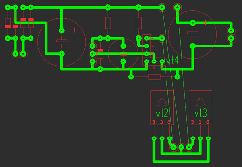
A rectifier is assembled on the diode bridge and capacitor C2, circuit C1 VD1 R3 is a reference voltage stabilizer, circuit R4 VT1 VT2 is a current amplifier for power transistor VT3, protection is assembled on transistor VT4 and R2, and resistor R1 is used for adjustment.
I took the transformer from an old charger from a screwdriver, at the output I got 16V 2A
As for the diode bridge (at least 3 amperes), I took it from an old ATX block as well as electrolytes, a zener diode, and resistors.
I used a 13V zener diode, but the Soviet D814D is also suitable.
The transistors were taken from an old Soviet TV; transistors VT2, VT3 can be replaced with one component, for example KT827.
Resistor R2 is a wirewound with a power of 7 Watts and R1 (variable) I took nichrome for adjustment without jumps, but in its absence you can use a regular one.
It consists of two parts: the first one contains the stabilizer and protection, and the second one contains the power part.
All parts are mounted on the main board (except for power transistors), transistors VT2, VT3 are soldered onto the second board, we attach them to the radiator using thermal paste, there is no need to insulate the housing (collectors). The circuit was repeated many times and does not need adjustment. Photos of two blocks are shown below with a large 2A radiator and a small 0.6A.

Indication
Voltmeter: for it we need a 10k resistor and a 4.7k variable resistor and I took an indicator m68501, but you can use another one. From resistors we will assemble a divider, a 10k resistor will prevent the head from burning out, and with a 4.7k resistor we will set the maximum deviation of the needle.
After the divider is assembled and the indication is working, you need to calibrate it; to do this, open the indicator and glue clean paper onto the old scale and cut it along the contour; it is most convenient to cut the paper with a blade.

When everything is glued and dry, we connect the multimeter in parallel to our indicator, and all this to the power supply, mark 0 and increase the voltage to volts, mark, etc.
Ammeter: for it we take a resistor of 0.27 ohm!!! and variable at 50k, The connection diagram is below, using a 50k resistor we will set the maximum deviation of the arrow.
The graduation is the same, only the connection changes, see below; a 12 V halogen light bulb is ideal as a load.
List of radioelements
| Designation | Type | Denomination | Quantity | Note | Shop | My notepad |
|---|---|---|---|---|---|---|
| VT1 | Bipolar transistor | KT315B | 1 | To notepad | ||
| VT2, VT4 | Bipolar transistor | KT815B | 2 | To notepad | ||
| VT3 | Bipolar transistor | KT805BM | 1 | To notepad | ||
| VD1 | Zener diode | D814D | 1 | To notepad | ||
| VDS1 | Diode bridge | 1 | To notepad | |||
| C1 | 100uF 25V | 1 | To notepad | |||
| C2, C4 | Electrolytic capacitor | 2200uF 25V | 2 | To notepad | ||
| R2 | Resistor | 0.45 Ohm | 1 | To notepad | ||
| R3 | Resistor | 1 kOhm | 1 | To notepad | ||
| R4 | Resistor |
Details
Diode bridge at the input 1n4007 or a ready-made diode assembly designed for a current of at least 1 A and a reverse voltage of 1000 V.Resistor R1 is at least two watts, or 5 watts 24 kOhm, resistor R2 R3 R4 with a power of 0.25 watts.
Electrolytic capacitor on the high side 400 volts 47 uF.
Output 35 volts 470 – 1000 uF. Film filter capacitors designed for a voltage of at least 250 V 0.1 - 0.33 µF. Capacitor C5 – 1 nF. Ceramic, ceramic capacitor C6 220 nF, film capacitor C7 220 nF 400 V. Transistor VT1 VT2 N IRF840, transformer from an old computer power supply, diode bridge at the output full of four ultra-fast HER308 diodes or other similar ones.
In the archive you can download the circuit and board:
(downloads: 1555)

The printed circuit board is made on a piece of foil-coated single-sided fiberglass laminate using the LUT method. For the convenience of connecting power and connecting output voltage, the board has screw terminal blocks.


12 V switching power supply circuit
The advantage of this circuit is that this circuit is very popular of its kind and is repeated by many radio amateurs as their first switching power supply and efficiency and times more, not to mention size. The circuit is powered from a mains voltage of 220 volts; at the input there is a filter which consists of a choke and two film capacitors designed for a voltage of at least 250 - 300 volts with a capacity of 0.1 to 0.33 μF; they can be taken from a computer power supply.
In my case there is no filter, but it is advisable to install it. Next, the voltage is supplied to a diode bridge designed for a reverse voltage of at least 400 Volts and a current of at least 1 Ampere. You can also supply a ready-made diode assembly. Next in the diagram there is a smoothing capacitor with an operating voltage of 400 V, since the amplitude value of the mains voltage is around 300 V. The capacitance of this capacitor is selected as follows, 1 μF per 1 Watt of power, since I am not going to pump large currents out of this block, then in my case, the capacitor is 47 uF, although such a circuit can pump out hundreds of watts. The power supply for the microcircuit is taken from the alternating voltage, here a power source is arranged, resistor R1, which provides current damping, it is advisable to set it to a more powerful one of at least two watts since it is heated, then the voltage is rectified by just one diode and goes to a smoothing capacitor and then to the microcircuit. Pin 1 of the microcircuit is plus power and pin 4 is minus power.

You can assemble a separate power source for it and supply it with 15 V according to the polarity. In our case, the microcircuit operates at a frequency of 47 - 48 kHz. For this frequency, an RC circuit is organized consisting of a 15 kohm resistor R2 and a 1 nF film or ceramic capacitor. With this arrangement of parts, the microcircuit will work correctly and produce rectangular pulses at its outputs, which are supplied to the gates of powerful field switches through resistors R3 R4, their ratings can deviate from 10 to 40 Ohms. Transistors must be installed N channel, in my case they are IRF840 with a drain-source operating voltage of 500 V and a maximum drain current at a temperature of 25 degrees of 8 A and a maximum power dissipation of 125 Watts. Next in the circuit there is a pulse transformer, after it there is a full-fledged rectifier made of four diodes of the HER308 brand, ordinary diodes will not work here since they will not be able to operate at high frequencies, so we install ultra-fast diodes and after the bridge the voltage is already supplied to the output capacitor 35 Volt 1000 μF , it is possible and 470 uF, especially large capacitances in switching power supplies are not required.

Let's return to the transformer, it can be found on the boards of computer power supplies, it is not difficult to identify it; in the photo you can see the largest one, and that is what we need. To rewind such a transformer, you need to loosen the glue that glues the halves of the ferrite together; to do this, take a soldering iron or a soldering iron and slowly warm up the transformer, you can put it in boiling water for a few minutes and carefully separate the halves of the core. We wind up all the basic windings, and we will wind our own. Based on the fact that I need to get a voltage of around 12-14 Volts at the output, the primary winding of the transformer contains 47 turns of 0.6 mm wire in two cores, we make insulation between the windings with ordinary tape, the secondary winding contains 4 turns of the same wire in 7 cores . It is IMPORTANT to wind in one direction, insulate each layer with tape, marking the beginning and end of the windings, otherwise nothing will work, and if it does, then the unit will not be able to deliver all the power.
Block check
Well, now let's test our power supply, since my version is completely working, I immediately connect it to the network without a safety lamp.Let's check the output voltage as we see it is around 12 - 13 V and does not fluctuate much due to voltage drops in the network.

As a load, a 12 V car lamp with a power of 50 Watts flows a current of 4 A. If such a unit is supplemented with current and voltage regulation, and an input electrolyte of a larger capacity is supplied, then you can safely assemble a car charger and a laboratory power supply.

Before starting the power supply, you need to check the entire installation and connect it to the network through a 100-watt incandescent safety lamp; if the lamp burns at full intensity, then look for errors when installing the snot; the flux has not been washed off or some component is faulty, etc. When assembled correctly, the lamp should be slightly flash and go out, this tells us that the input capacitor is charged and there are no errors in the installation. Therefore, before installing components on the board, they must be checked, even if they are new. Another important point after startup is that the voltage on the microcircuit between pins 1 and 4 must be at least 15 V. If this is not the case, you need to select the value of resistor R2.

This power supply on the LM317 chip does not require any special knowledge for assembly, and after proper installation from serviceable parts, it does not require adjustment. Despite its apparent simplicity, this unit is a reliable power source for digital devices and has built-in protection against overheating and overcurrent. The microcircuit inside itself has over twenty transistors and is a high-tech device, although from the outside it looks like an ordinary transistor.
The power supply of the circuit is designed for voltages up to 40 volts alternating current, and the output can be obtained from 1.2 to 30 volts of constant, stabilized voltage. Adjustment from minimum to maximum with a potentiometer occurs very smoothly, without jumps or dips. Output current up to 1.5 amperes. If the current consumption is not planned to exceed 250 milliamps, then a radiator is not needed. When consuming a larger load, place the microcircuit on a heat-conducting paste to a radiator with a total dissipation area of 350 - 400 or more square millimeters. The selection of a power transformer must be calculated based on the fact that the voltage at the input to the power supply should be 10 - 15% greater than what you plan to receive at the output. It is better to take the power of the supply transformer with a good margin, in order to avoid excessive overheating, and be sure to install a fuse at its input, selected according to the power, to protect against possible troubles.
To make this necessary device, we will need the following parts:
- Chip LM317 or LM317T.
- Almost any rectifier assembly or four separate diodes with a current of at least 1 ampere each.
- Capacitor C1 from 1000 μF and higher with a voltage of 50 volts, it serves to smooth out voltage surges in the supply network and the larger its capacitance, the more stable the output voltage will be.
- C2 and C4 – 0.047 uF. There is a number 104 on the capacitor cap.
- C3 – 1 µF or more with a voltage of 50 volts. This capacitor can also be used with a larger capacity to increase the stability of the output voltage.
- D5 and D6 - diodes, for example 1N4007, or any others with a current of 1 ampere or more.
- R1 – potentiometer for 10 Kom. Any type, but always a good one, otherwise the output voltage will “jump”.
- R2 – 220 Ohm, power 0.25 – 0.5 watts.
Assembling an adjustable stabilized power supply
I assembled it on a regular breadboard without any etching. I like this method because of its simplicity. Thanks to it, the circuit can be assembled in a matter of minutes.


Checking the power supply
By rotating the variable resistor you can set the desired output voltage, which is very convenient.DC power supplies are needed not only by radio amateurs. They have a very wide scope of application, and therefore most home craftsmen use them to one degree or another. This article describes the main types of voltage converters, their characteristic differences and applications, and how to make a simple power supply with your own hands.
Doing it yourself will save you a lot of money. Once you understand the device and operating principle, you can easily repair this device.

Areas of use
These devices have a very wide range of applications. Let's look at the main uses. To save battery life, low-voltage power tools are connected to homemade power supplies. Such devices are used for connecting LED lighting devices, installing lighting in rooms with high humidity and danger of electric shock, and for many other purposes not directly related to radio electronics.


Device classification
Most power supplies convert AC mains voltage of 220 volts into DC voltage of a given value. Moreover, the device is characterized by a large list of operating parameters that must be taken into account when purchasing or designing.

The main operating parameters are output current, voltage and the ability to stabilize and adjust the output voltage. All these converters are classified into two large groups according to the conversion method: analog and pulse devices. These groups of power supplies have strong differences and are easily distinguished from the photo at first glance.

Previously, only analog devices were produced. In them, voltage conversion is carried out using a transformer. Collecting such a source is not difficult. Its scheme is quite simple. It consists of a step-down transformer, a diode bridge and a stabilizing capacitor.

Diodes convert AC voltage to DC voltage. The capacitor further smoothes it out. The disadvantage of such devices is their large dimensions and weight.

A 250-watt transformer weighs several kilograms. In addition, the voltage at the output of such devices can change due to external factors. Therefore, to stabilize the output parameters in such devices, special elements are added to the electronic circuit.

High-power power supplies are manufactured using transformers. It is advisable to use such devices for charging car batteries or for connecting electric drills to save the life of lithium batteries.

The advantage of such a device is the galvanic isolation between the two windings (with the exception of autotransformers). The primary winding connected to the high voltage network has no physical contact with the secondary winding. A reduced voltage is generated on it.

Energy transfer is carried out using an alternating current magnetic field in the metal core of the transformer. If you have minimal knowledge in radio electronics, it is easier to assemble a classic adjustable power supply using a transformer with your own hands.


With the development of electronic technology, it has become possible to produce cheaper semiconductor voltage converters. They are very compact, light in weight and have a very low price. Thanks to this, they became market leaders. Every apartment uses several different power supplies.

Unfortunately, most modern devices do not have galvanic isolation from the power supply. Because of this, quite often people die who use the device while charging a cell phone or other equipment and at the same time take a bath or wash their face.

If safety precautions are followed, there is no danger to a person. These devices are quite low in cost and when they break down, they often do not try to repair them, but purchase a new device. However, if you understand the circuits and operating principles of switching power supplies, you can easily both repair such a power supply and assemble a new device.

Switching power supplies
Let's look at the design and operating principle of switching power supplies. In such devices, the alternating mains voltage is converted into high-frequency voltage at the input. To transform high-frequency currents, it is not large transformers that are required, but miniature electromagnetic coils. Therefore, such converters easily fit into small housings. For example, they can easily be placed in the plastic socket of an energy-saving lamp.


The layout of such a power supply in a small device does not cause any problems. For reliable operation, it is necessary to provide the possibility of cooling the heating elements of the electronic circuit on special metal radiators. The converted voltage is rectified using high-speed diodes and smoothed at the output filter.

The disadvantage of such devices is the inevitable presence of high-frequency interference at the output of the converter, despite the presence of special filters. In addition, pulsed devices use special output voltage stabilization circuits.


The switching power supply can be purchased as a separate unit, ready for installation in the device. You can also assemble this device yourself using widely available diagrams and instructions for assembling power supplies.

It should be taken into account that self-assembly may be more expensive than a purchased product purchased online in the Asian market. This may be due to the fact that electronic components are sold at a higher markup than the manufacturer's markup in China for the assembly of the product and its delivery. In any case, having understood the structure of such devices, it will be possible not only to assemble such a device yourself, but also, if necessary, to repair it. Such skills will be very useful.

If you want to save money, you can use switching power supplies from personal computers. Often, a faulty personal computer contains a working unit. They require minimal modification before use.

Such power supplies have idle protection. They must be under load at all times. Therefore, in order to avoid shutdown, a constant resistance is included in the load. Such modernized units are used primarily to power household power tools.

DIY photo of power supplies


