Manifold (mixing unit) for water heated floor. How to make a manifold for polypropylene pipes? DIY manifold for heated floors made of polypropylene
The underfloor heating system is the only trouble-free and more efficient alternative to traditional heating. Underfloor heating can also be used as an addition to a conventional scheme, for example for one or more rooms. Its advantage is that the system always works autonomously and does not depend on the main heating circuit. Such autonomy is provided by a do-it-yourself underfloor heating manifold, which works as a multifunctional device. What is the multitasking of the collector in the “warm floor” system?
Collector device
First of all, let’s look at the concept of “warm floor”. This is an autonomous heating system connected to the main heating ring. To make the connection as efficient as possible and to avoid heat losses at the junction points, a collector connection is used (in some cases, several collectors if there are several heating circuits in the system). The most primitive collector for a warm water floor is a section of a heat-conducting pipe from which there are bends for connecting other heating pipes. 
That is, a collector is a pipe circuit for distributing coolant that directs and regulates the flow of hot water through the heating pipes in the house. The standard connection of a heated floor collector is as follows: the collector input is connected to the return or coolant supply (depending on the heating circuit), the device outputs are connected to the heated floor pipe system.
The underfloor heating collector is controlled and configured manually or automatically. For automatic operation, it is necessary to install a control unit or servo drive. The control device includes supply valves - two- or three-way. Supply valves differ from conventional valves in their ability to pass coolant in one direction. You need to install the valves especially carefully - if you install the valve in the opposite direction, it will quickly break.
The shut-off element of the supply valve is a steel ball or rod. When the valve handle is turned, the hole is blocked, and the rotation itself can be done manually or using servos connected to temperature sensors. 
A two-way mixing valve allows coolant to flow in one direction, regulating the amount of hot liquid. The adjustment occurs smoothly and slowly due to the small throughput of the device.
There are several technical solutions for mixing valves, and one of them is a thermostat with a liquid sensor. Such a thermostatic head controls the temperature of the coolant in the heating circuit by opening or closing the valve, thereby regulating the supply of hot coolant flowing from the boiler into the system. The thermostat is turned on in the collector so that coolant is supplied continuously from the return pipe, and from the heating apparatus - as needed.
Thus, installing a manifold with a two-way valve ensures a constant and comfortable temperature of the coolant throughout the entire underfloor heating pipeline, and smooth temperature control is ensured by the low throughput of the device. Two-way valves are easy to install and replace, they are reliable and durable. Their only drawback is that it is not recommended to be included in heating systems that are designed for a large heating area (≥ 200m2).

The three-way supply valve has a more complex and multifunctional device, combining the capabilities of a bypass and bypass valve in one housing. The body of a three-way manifold valve has one outlet and two inlets, and the coolant is adjusted in the same way as in a two-way device - either with a steel ball or a rod. The difference between this valve is that neither the ball nor the stem completely blocks the flow of coolant, and the design itself is designed to redistribute and mix return and supply. To automatically regulate the temperature, a servo drive is built into the valve, powered by signals from temperature sensors and controllers. The servo drive controls the shut-off valves in the structure, ensuring the desired degree of flow mixing. 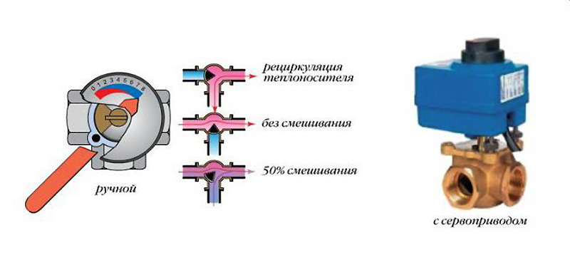
Three-way supply valves are installed in manifold units for large-area heated rooms - ≥ 200 m2, as well as in multi-circuit heating systems.
For heated floors, a common collector unit is most often installed, or a separate collector is installed in front of each heating circuit. If the latter option is implemented, then all collectors are equipped with flow meters, thermostats, as well as the following elements:
- Return and supply mixing valve;
- Shut-off valve for balancing the heating device;
- Overflow valve.
You can assemble a collector for a heated floor yourself using different schemes, and in some schemes of collector units bypasses are used, but not always - only in single-circuit systems. If the underfloor heating system is organized according to a dual-circuit scheme, then the collector can be connected without a bypass to the secondary circuit. 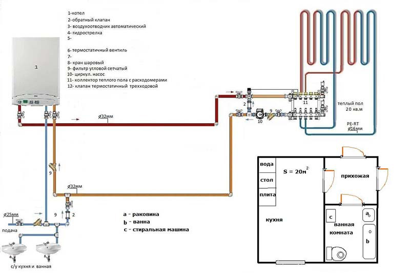
Before assembling a manifold assembly for a heated floor, weigh your options - sometimes it’s easier to buy a ready-made structure. If you are going to buy a collector, it is better that all its parts and elements are from the same manufacturer. When assembling the unit yourself, you must select the material from which the main components of the unit will be assembled: copper, steel, polymers or brass.
Also, when choosing an industrial design, it is important to consider the following parameters:
- How many heating circuits will there be in the system (usually from 2 to 12), the total length of the pipeline and the capacity of the circuits;
- Maximum permissible pressure in pipes;
- Possibility of expanding the heating system;
- Manual or automatic collector control;
- Electrical power of all components and assemblies;
- The diameter of the internal holes of the collector (throughput).

The most efficient operation of the assembled collector units can be ensured by connecting heating circuits of equal length to them. In order to equalize the length of the pipelines with sufficient accuracy, they are divided into equal sections, which are connected to the collector. The easiest way is to calculate the collector unit in a special computer program or on an online calculator, so that the phenomenon called “thermal zebra” does not appear, that is, uneven heating of the floor.
For the calculation you will need the following data:
- Type of decorative floor covering;
- the area of the heated room and the plan for placing large objects in it;
- Material and diameter of circuit pipes;
- Boiler rated power;
- Type of floor insulation.
Important: when laying underfloor heating pipes, it is necessary to avoid pipe joints - this is prohibited by existing standards. It is also necessary to remember that the hydraulic resistance of the coolant increases with each turn of the pipeline and with increasing its length.

When designing a heated floor system, you first need to find the optimal location for installing the collector. Typically, the unit is installed in a manifold cabinet, and the cabinet itself is mounted at a height of 30-40 cm from the floor level next to the supply and return.
In order not to blame your own mistakes and ensure maximum heating of the heated floor pipes, study the instructions for connecting the collector. Then assemble the unit in the following sequence (this applies to an industrial manifold unit):
- Unpack the tubes for forward and reverse coolant supply. The tubes must have flow meters and supply valves. If the collector is multi-sectional, assemble the sections into one structure;
- From the assembled sections you need to assemble a unit on brackets (included in the kit);
- Next, we install shut-off valves, automation, sensors and other connecting fittings;
- We attach the unit to the wall or in a cabinet, install a thermostat, a servo drive and a circulation pump;
- We connect the pipes from the boiler and the pipes from the heating circuits of the “warm floor” system.

Now the connection diagram for the heated floor collector is pressed, after which the concrete screed can be poured. Thermal adjustments of the collector can be carried out after installation of the finishing coating.
DIY collector unit
A factory manifold is a fairly expensive product, so many craftsmen want to make it themselves. You will still have to buy many elements, but the cost will be cheaper. The easiest way is to solder a homemade manifold from PVC pipes and fittings Ø 25-32 mm. You will also need tees and bends of the same diameters, and shut-off valves.
Important: a homemade collector assembly has many joints, so all soldering must be carefully checked, and not only during assembly, but also during operation of heated floors.

The number of valves and fittings is calculated by the number of heating circuits. The tools you need are a soldering iron for propylene elements and attachments for it, special scissors for cutting pipes and a tape measure.
Marking the collector consists of marking and cutting pipes of the required length, observing the minimum distance between the tees. Valves and transitions are soldered to the PVC tees with a soldering iron. Fittings for connecting the pump are soldered to this structure. As you can see, everything is simple, but it is better to buy more complex collector units ready-made.
When designing heating and plumbing systems, it is often necessary to break down the number of fluid flows. For example, in heating systems with several circuits it is simply impossible to do without coolant distribution. One of the means to achieve the goal is a distribution manifold.
A manifold is a device for distributing liquid, which is often called a comb, apparently due to the external similarity of the manifold circuit with this object. In plumbing systems it is intended to distribute water, for example, from a supply pipe to several taps without loss of pressure.
Accordingly, if two people, for example, use water in the bathroom and in the kitchen, the pressure in the pipes and the water pressure will be equal for both.
The collector simplifies the distribution of water to different places; you can easily make connections to a washing machine, bathtub, sink, or drain tank. There is one target pipe from the collector to the consumer without unnecessary wiring and soldering, which not only simplifies, but also increases the reliability of the system.
In heating systems, combs are used to distribute coolant along circuits; heating is usually divided into sections. For example, the first circuit is a radiator heating system, the second is a warm floor on the same floor. In this case, it is necessary to distribute the coolant from the heater to the circuits and create a return closed system.
Without a collector, such a design will be extremely complex, it will require much more effort and material in order to implement heating, it will be labor-intensive to maintain and less reliable in operation.
The collector distributes the coolant with uniform pressure and returns the coolant from all circuits back to the heater. This method makes the closed system simple and reliable.
It is important! The main factor in the performance of the comb is that the inlet hole for the liquid must have a diameter equal to or larger than the outlet holes.
Characteristics of polypropylene collectors
Polypropylene is non-toxic and, during normal use, completely harmless to both the user and the environment. The material can only release harmful vapors when burning. The melting point of polypropylene is 160 – 170 ºC.
When installing a water heated floor, it is important to connect it correctly. Therefore, the circuits are not connected to the boiler directly, but through manifolds, sensors, valves and pumps. If you buy a ready-made mixing unit, the price will cost you 10-20 thousand rubles.
In this article we will tell you how you can save money and assemble a heated floor collector with your own hands.
Why do you need a collector?
A collector is a technical element that mixes and distributes coolant from different parallel heating circuits. Due to its large cross-section and low speed, it allows you to mix warm and hot coolant in it, leveling the specified parameters.

The connection diagram is designed in such a way that after the hot liquid passes through the circuit, it cools down and returns to the manifold for mixing through the return pipe. To regulate the ratio of warm and hot water, special valves are installed, and to control the temperature, heat sensors, outdoor weather sensors, and pressure sensors are installed. To increase the pressure in the system, the manifold assembly may include a circulation pump.
Now let’s imagine an example: you have heating radiators connected to the boiler in your house, which require a coolant temperature of 75-95 degrees for normal operation. You also want to connect a heated floor to the boiler, but the water temperature in it should not be higher than 35-55 degrees. Otherwise, you will violate sanitary standards (maximum floor surface temperature is 30 degrees), ruin the finishing floor covering, and it will release harmful substances.
In such a situation, you cannot do without a collector. You will need to send colder water to the warm floor circuits of your apartment or house than to the radiators. In addition, due to the large length of the pipes, it will be necessary to increase the pressure in the system, so an additional pump will be required.

Elements of the collector unit
The diagram of a conventional mixing unit consists of the following parts:
- Mixing two or three way valve;
- Circular pump;
- Balancing and shut-off valves;
- Collector (2 pcs.);
- Thermal head with sensor for temperature control;
- Pressure gauges for pressure control;
- Air vent to remove air from the system;
- In addition, you will need various fittings, nipples, tees and other connecting elements.

Two way valve

- The thermal head controls the temperature of the liquid entering the circuits.
- As soon as the temperature becomes high, it closes the valve and the hot water supply decreases.
- When the coolant cools down, it opens the hot water supply more.
- In this case, coolant is supplied from the return in a constant mode, and hot water is supplied only when necessary.
The two-way valve has a low throughput, so the supply of hot coolant occurs smoothly and without sudden jumps. This type is mainly used for mixing, but it is only suitable for rooms of less than 200 square meters.
Advice!
Like any faucet, the valve can become clogged over time, so for easy replacement it is recommended to install it on an American split coupling.

Three-way valve
- The three-way valve simultaneously balances the water supply from the boiler and the return water through the bypass.
- Its main difference is the mixing of the coolant inside itself.
- Inside it there is a damper, which is perpendicular to the supply and return pipes.
- By changing its position, the water supply ratio is adjusted and the temperature changes.

Experts consider this option to be universal and use it in complex heating systems with a large number of circuits and automatic adjustment.
The disadvantages include possible sharp temperature fluctuations, and hot water may enter the circuit if the thermostat readings are incorrect. This valve has a high flow rate, so even a small movement of the valve can make a big difference in temperature.
Often, such valves are equipped with servos that are controlled by weather sensors or air temperature sensors.
Weather sensors
To be able to regulate the temperature automatically, depending on the weather outside the window, weather-dependent sensors are connected to the underfloor heating system. When there is a sudden cold snap, the room will cool down faster, so increased heating will be required. To increase the efficiency of underfloor heating, you will need to increase the temperature and coolant flow.
Of course, you can adjust everything manually, but this way you will not be able to find the optimal feed ratios. That's why weather-dependent controllers are used. They check the temperature every 20 seconds, and if it does not correspond to the optimal values, they change the valve position by 1/20th. More advanced controllers can reduce water flow when no one is home.
Assembly diagram
After you have purchased all the necessary elements, you can make a homemade manifold for a heated floor. To do this, assemble the elements according to one of the schemes shown in the photo.


Advice!
You can assemble a manifold for a warm floor with your own hands in a special internal or external cabinet.
External cabinets are 12-16 cm wide, so not every pump will fit into them.
The inner closet can be slightly enlarged by deepening the back wall.
Conclusion
When connecting underfloor heating pipes to the manifold, use special compression fittings. Before doing this, it is recommended to make a small chamfer on the pipe so that it fits tightly into the socket.
In a private home it is a costly business. However, for the reliable operation of such a system, savings are inappropriate. But despite this, there are options on how to reduce the cost of the heating system. For example, instead of buying a new manifold, you can put in a little effort and make it yourself. This article will discuss the question of how to make a manifold for a heated floor with your own hands, using polypropylene.
Polypropylene is successfully used in modern heating systems. With the correct calculation of the pipe diameter, you can make a warm floor from polypropylene pipes.
A distribution manifold can also be assembled from polypropylene fittings. To do this you will need the following components:
- Pipes Ø25 and Ø32 mm.
- Plugs Ø32 mm.
- Couplings 32×1″ and 25×3/4 with internal thread.
- American ball valves.
- Couplings 25×3.4 with external thread.
- Security group.
- Tees Ø25 and Ø32 mm.
- Sealant.
- Automatic air vent.
Construction and installation of the collector

As a rule, the collector consists of two parts and ours will not be an exception. Its first part is intended for uniform distribution of hot coolant through the pipes from the boiler.
When producing a manifold for a heated floor from polypropylene, make an additional outlet in case of adding a heating circuit.

All components of the comb are connected by thermal welding using special equipment. Connect a safety group and an air vent to one of the parts of the manifold. A tap is also connected, which in case of repair will serve to drain the coolant from the system. As for the other part of the collector, to which the return pipes will be connected, a tap and an air vent are mounted on it in the same way. Moreover, a circulation pump is installed on the return line, which will create forced movement of the coolant through the heating circuits. It must be installed with the arrow pointing towards the boiler.

To create an economical water-heated floor system, it is recommended to install a three-way valve after the circulation pump. The system is also additionally equipped with a check valve.
So, making a comb from polypropylene is not difficult. It is important to follow the outlined schemes. For a warm water floor, the collector will serve as an excellent means of evenly distributing thermal energy over the entire floor area. If you still have questions about how to assemble a collector, write questions to our experts or leave comments at the end of this article.
Video
From the provided video materials you will learn how to make a manifold for a warm water floor from polypropylene:
1.
2.
3.
4.
It is accepted that the installation of a heated floor collector begins with the arrangement of a niche in the wall where it is supposed to place a cabinet for it. The dimensions of this special box are usually 60x40x12 centimeters. The place where the distribution manifold for heated floors is mounted should be located directly next to the surface of the floor covering.
The need to install a manifold cabinet
The cabinet in which the manifold for heating and underfloor heating will be located, shown in the photo, is necessary to hide this element of the heating system. It is also the place where heating pipes are connected to other structural parts for heating the premises. Devices for regulating the supply of coolant and the functioning of the heated floor are also installed here.Some owners of private houses prefer to install a manifold for underfloor heating with their own hands. After the special cabinet is ready, the coolant supply and return pipes are installed into it. The first of them supplies hot water to the system from the boiler, and the second collects the cooled coolant and returns it back to the place of heating.
To ensure that the movement of water is continuous, perform. Shut-off valves are installed at the ends of the supply and return pipelines. Thus, if it is necessary to turn off the heating in one of the rooms or in a certain part of the building, you need to close these two taps, which will not affect the heat supply to the rest of the rooms in the house. To connect a plastic pipeline to a metal valve, a compression element is used - a fitting.
Collector as an element of the heating system
The valves must be connected to the manifold. It is a piece of pipe that has several outlets on one side. The collector input must be connected to a valve. Using special fittings, the heated floor collector is connected to the metal-plastic heating circuits of the heating system.
A distribution manifold with several branches has an outlet at the opposite end of the pipe. It is closed either with a regular plug, or a splitter is installed - it has a drain valve on one side, and an air vent on the other, which automatically removes air accidentally formed in the system.
Both pipelines are arranged in a similar way - both the supply and return directions. For this reason, when installing a manifold for a heated floor with your own hands or a team of specialists, the comb and other necessary parts are purchased in pairs.
A warm floor and heating manifold is installed, taking into account the location of the main pipe system intended for the heating boiler, and the configuration of the pipelines to provide heat to individual rooms. It is advisable to have it performed by an experienced specialist.

As a rule, a do-it-yourself heated floor collector is mounted in a wall space in such a way that its location is equidistant from the end points of the heat pipes. Thanks to this, it is possible to ensure optimal operating conditions for the heating system. In the case when heat supply is necessary for a large number of rooms and utility rooms, it is advisable to provide in advance several distribution units for the coolant liquid (read also: "").
Installation of a warm water floor, detailed in the video:
Components of the collector group
The collector group for heated floors includes:- comb-pipelines, which represent tees connected according to the “TTT” scheme;
- mixing unit with three-way valve;
- supply manifold with control valves for water flow to the branches;
- return manifold - adjusting valves operating in automatic mode with a servo drive;
- a circulation pump having a drainage device;
- devices for and automation of the heat supply process.

As the connection diagram for the underfloor heating manifold provides, the hot coolant enters the mixing unit for the water heating system, in which the supply and return water are mixed to ensure the heat supply mode (read also: " ").
The fittings installed on the combs are responsible for supplying a heat source to the individual circuits of the mounted system and at the same time controls the design of the heated water floor. When a certain (set) temperature in the room is reached, automatic valves block the access of the coolant liquid to the heating circuits. A manifold for underfloor heating with flow meters ensures economical consumption of energy resources.
You can purchase a manifold for a warm water floor as a complete set, or each of its parts separately. When the decision is made to install a collector group, it should be remembered that the pump unit must be equipped with a drain valve to ensure drainage in one of the sections of the heating system. In addition to the drainage device, the collector must have an air exhaust system installed at its highest point.
In addition, comb-pipelines must be equipped with special indicating and measuring devices, such as pressure gauges - thermometers, pulse devices connected to heating sensors in the screed.

Particular attention should be paid to the correct installation of the collector unit for a water floor heating system - how warm and cozy it will be in the house depends on its operation (read: " "). Before connecting the heated floor collector, it is necessary to complete a detailed layout of all elements that provide heat supply and carry out installation in accordance with the plan. Otherwise, eliminating the shortcomings will cost a significant amount.
After completing the installation of all elements of the manifold cabinet, a test run of the system is performed in order to detect errors and defects. The operating pressure in it should be approximately 25% higher than this figure required for continuous operation.