How to assemble good acoustics for your home. Do-it-yourself speaker system
A characteristic feature of counter-aperture is that the sound coming to the listener from virtually all directions, although it creates an impressive presence effect, cannot fully convey information about the sound stage. Hence the stories from listeners about the feeling of a piano flying around the room and other wonders of virtual spaces.
Counterperture
Pros: A wide zone of spectacular volumetric perception, naturalistic timbres thanks to the non-trivial use of wave acoustic effects.
Cons: The acoustic space is noticeably different from the sound stage conceived when recording the phonogram.
And others...
If you think that this is the end of the list of speaker design options, then you greatly underestimate the design enthusiasm of electroacoustic speakers. I described only the most popular solutions, leaving behind the scenes a close relative of the labyrinth - a transmission line, a bandpass resonator, a housing with an acoustic resistance panel, load pipes...
 Nautilus from Bowers & Wilkins is one of the most unusual, expensive and reputable speaker systems. Design type - loading pipes
 This kind of exoticism is quite rare, but sometimes it materializes in a design with a truly unique sound. And sometimes not. The main thing is not to forget that masterpieces, like mediocrity, are found in all designs, no matter what the ideologists of a particular brand say.
At first glance, making your own speakers is quite simple. However, this is misleading. First of all, it should be noted that the models are made with different elements. Depending on them, the device parameters and sound quality will be different.
There are special requirements for computer speakers. You can also make a model for your car or studio yourself. In this case, it is very important to follow the instructions. First of all, for assembling speakers you should consider standard scheme models.
Speaker layout
The speaker circuit includes drivers, pads, diffuser and crossover. Powerful models use a special bass reflex. Amplifiers can be installed with field-effect or switching transistors. To improve sound quality, capacitors are used. The woofer is matched with the amplifier. The dynamic head must be attached to the seal.

Single speaker models
Single speaker speakers are very common. To assemble the model, you will first have to deal with the body. Plywood is often used for this purpose. At the end of the work it will have to be sheathed. However, first of all you should make side racks. For this purpose you will have to use a jigsaw. you can't pick up high power.
The inside of the plywood must be stitched with vibration-proof tape. After fixing the speaker, the seal is fixed. Glue is used for this purpose. Next, all that remains is to attach the diffuser. Some people make a separate shelf for it and fix it with stacking screws. To connect the speaker to the plug, a terminal block is installed. How to turn on speakers? For this purpose, a cable is used from the terminal block, which should lead to a power source.
Model drawing for two speakers
Speakers with two speakers can be made for home or car. If we consider the first option, then a pulse type diffuser will be required. First of all, durable plywood is selected for assembly. The next step is to cut out the bottom post. Models with legs are very rare. To cover the veneer, you can use regular varnish. There is no need to glue vibration-proofing tape to the front pillar. The diffuser is mounted under the speaker. To make a hole in the panel, you need to use a jigsaw. The bass reflex is fixed at the rear wall. Some manufacture devices with horizontal speakers. In this case, the diffuser will be located at the top of the structure. Wires for speakers are of the two-core type.

Devices with three speakers
Speakers (homemade) with three speakers are very rare. These devices are most suitable for the multi-channel type. To assemble the model, first of all, sheets of plywood are selected. Some also recommend using veneers. However, models made of natural wood are quite expensive on the market. The speakers should be installed horizontally. The device will also require an amplifier.
Metal corners are used to secure it. To connect the plates you will need tightening screws. In some cases, the plates are secured with glue. Next, the model will have to be partially covered with leatherette. The next step is to install the terminal block. In order to fix it on the body, you will need to make a separate hole. It is also important to note with regulators. Microcircuits for them are used of the capacitor type. When the speakers produce noise, you need to change the diffuser.
Studio devices
Speaker drawings for studios assume the use of powerful speakers. The diffuser is most often used of the pulse type. Many experts recommend installing two amplifiers. For normal operation you will need a zener diode.
In order to assemble the speakers yourself, the housing is first made. Round holes are made on the front panel for the speakers. You will also need a separate output for the bass reflex. The design of the columns is quite different. Some people prefer to varnish the surface of the case. However, there are models covered in leather.

Models for computers
Speakers for computers are often made with one speaker. To assemble the model, veneer sheets of small thickness are selected. A hole for the speaker is cut out on the front panel. The bass reflex must be located at the rear of the housing. If we consider low-power models, the amplifier can be used without a resistor.
To adjust the speaker volume, special crossovers are used. These elements are allowed to be installed on a bass reflex. If we consider devices with a power of more than 100 W, then amplifiers can only be used with resistors. Some people select pulse diffusers for the model. At the end of the work, the terminal block is always installed.
Automotive modifications
Available with two or three speakers. To assemble the model yourself, you will need sheets of plywood. In some cases, varnished veneer is used. To fix the speaker, you need to make a hole in the panel. The next step is to install the bass reflex. Some modifications are made with low-frequency cores. If we consider speakers (homemade) of low power, then the bass reflex can be installed without an amplifier.
In this case, a multi-channel crossover is used to control sound. Some specialists install terminal blocks behind the bass reflex. If we consider speakers with a power of more than 50 W, then the microcircuits are used for two amplifiers. The diffuser is installed as a standard pulse type. Before fastening the case together, it is important to take care of the vibration-proofing layer. For the terminal block, you need to make a separate hole on the plate. Some people believe that the body must be cleaned. The wires for the speakers are of the two-wire type.

Open-back speakers
Portable speakers with an open case are quite easy to make. Most often they are made with one speaker. Holes are made on the back panel of the device with a drill. The plates are directly connected with tightening screws. The diffuser for such devices is suitable for pulse type. Bass reflex units are often installed with one amplifier. If we consider powerful portable speakers, they use a resistor crossover. It is attached to the bass reflex. Many experts recommend installing speakers on a seal.
Devices with closed housing
Speakers (homemade) with a closed housing are considered the most common. Many experts believe that they are the best in sound quality. Bass reflex devices are suitable operational type. The woofers are installed in the holes. For the purpose of assembling the case, ordinary sheets of plywood are suitable. It is also important to note that there are modifications with cores. If we consider high-power speakers, the terminal blocks are installed in the lower part of the housing. The design of the models is quite different.

20 W models
Assembling 20V speakers is quite simple. First of all, experts recommend preparing six sheets of veneer. They should be varnished at the end of the work. It makes more sense to start assembly by installing the speakers. The bass reflex is used as a pulse type. In some cases it is installed on pads. Experts also recommend using rubber seals.
Power supply to the speakers is provided through the terminal block. It is attached to the back panel. The bass reflex can be installed either with or without an amplifier. If we consider the first option, then the cores are selected of the phase type. In this case, the woofer does not need to be used. If we consider speakers without an amplifier, then they use a crossover. At the end of the work, it is important to clean the body and varnish it.
50 W devices
Speakers (homemade) rated at 50 W are suitable for ordinary acoustic players. In this case, the body can be made from regular plywood. Many experts also recommend using natural wood veneer. However, it is important to note that he is afraid of high humidity.

After choosing the material, you should work on the speakers. They must be installed next to the bass reflex. In this case, you cannot do without an amplifier. Many experts recommend selecting only low-frequency crossovers. If we consider modifications with a regulator, then they use a pulse diffuser. The terminal block in this case is installed last. You can always use leatherette to decorate the speakers. More simple option is considered to be coating the surface with varnish.
Speakers with a power of 100 W
100 W speakers are suitable for powerful ones. In this case, the bass reflex is taken only of the pulse type. It is also important to note that the amplifier is installed with a crossover. Many experts recommend using veneer to assemble the case. It is better to install the woofer on a pad.
Before a detailed consideration of the problem, we will outline the range of tasks; knowing the final goal, it will be easier to choose the right direction. Making speaker systems with your own hands is a rare occurrence. Practiced by professionals and novice musicians when store options not satisfied. The problem arises of integrating into furniture or high-quality listening to existing media. These are typical examples that can be solved using a set of generally accepted methods. We'll take a look at it. We do not recommend scrolling diagonally through the speaker system, delve into it!
Acoustic system design
There is no chance of making an acoustic system yourself without understanding the theory. Music lovers should know that the biological species Homo Sapiens hears sound vibrations with frequencies of 16-20,000 Hz through the inner ear. When it comes to classical masterpieces, the variation is high. The lower edge is 40 Hz, the upper edge is 20,000 Hz (20 kHz). The physical meaning of this fact is that not all speakers are capable of reproducing the full spectrum at once. Relatively slow frequencies are better handled by massive subwoofers, and squeaking at the lower edge is reproduced by smaller speakers. Obviously, this means nothing to most people. And even if part of the signal disappears or is not reproduced, no one will notice it.
We believe that those who set the goal of making their own acoustic system should critically evaluate the sound. It will be useful to know that a suitable speaker has two or more speakers in order to be able to reflect the sound of a wide swath of the audible spectrum. But even in complex systems there is only one subwoofer. This is due to the fact that low frequencies cause the environment to vibrate, even penetrating through walls. It becomes unclear where exactly the bass is coming from. Consequently, there is only one low-frequency speaker – a subwoofer. But as for other things, a person will confidently say from which direction this or that special effect came (the ultrasound beam is blocked by the palm).
In connection with the above, we will divide the acoustic systems:
- Sound in Mono format is unpopular, so we avoid touching on historical excursions.
- Stereo sound is provided by two channels. Both contain low and high frequencies. Equal speakers equipped with a pair of speakers (bass and squeak) are better suited.
- Surround Sound is distinguished by the presence of a larger number of channels, creating a surround sound effect. We avoid getting carried away with subtleties; traditionally, 5 speakers plus a subwoofer convey the range to music lovers. The design is varied. Research is still underway to improve the quality of acoustic transmission. The traditional arrangement is as follows: in the four corners of the room (roughly speaking) there is a speaker, the subwoofer is on the floor to the left or in the center, the front speaker is placed under the TV. The latter is in any case equipped with two or more speakers.
It is important to create the correct enclosure for each speaker. Low frequencies will require a wooden resonator, but for the upper end of the range it doesn’t matter. In the first case, the sides of the box serve as additional emitters. You will find a video demonstrating the overall dimensions corresponding to the wavelengths of low frequencies according to science, practically all that remains is to copy ready-made designs; the topic is devoid of relevant literature.
The range of tasks is outlined, readers understand that a homemade acoustic system is built with the following elements:
- a set of frequency speakers according to the number of channels;
- plywood, veneer, body boards;
- decorative elements, paint, varnish, stain.
Acoustics design
Initially, select the number of columns, type, location. Obviously, producing more channels than a home theater has is an unwise tactical move. A cassette recorder will only need two speakers. At least six buildings will be released for the home theater (there will be more speakers). According to the needs, accessories are built into the furniture, the quality of low frequency reproduction is poor. Now the question of choosing speakers: in the publication by Naidenko and Karpov the nomenclature is given:

- Low frequencies - CA21RE (H397) head with an 8-inch fit.
- Mid range - MP14RCY/P (H522) 5" head.
- High frequencies – head 27TDC (H1149) by 27 mm.
Brought basic principles designing acoustic systems, offered electrical diagram a filter that cuts the flow into two parts (a list of three subranges is given above), the name of purchased speakers was given that solve the problem of creating two stereo speakers. We avoid repetition; readers can take the trouble to look through the section and find specific titles.
The next question will be the filter. We believe that National Semiconductor will not be offended if we screenshot the drawing of the Ridico translation amplifier. The figure shows an active filter with power supply +15, -15 volts, 5 chips of the same type ( operational amplifiers), the limiting frequency of the subbands is calculated by the formula shown in the image (duplicated in text):
P – number Pi, known to schoolchildren (3.14); R, C – resistor and capacitance values. In the figure, R = 24 kOhm, C is silent.

Active filter powered by electric current
Taking into account the capabilities of the selected speakers, the reader will be able to select a parameter. The characteristics of the speaker's playback band are taken, the overlap junction between them is found, and the cutoff frequency is placed there. Thanks to the formula, we calculate the value of the capacitance. Avoid touching the resistance value, reason: it can (disputed fact) set the operating point of the amplifier, the transmission coefficient. On frequency response given in the translation, which we omit, the limit is 1 kHz. Let's calculate the capacity of the specified case:
C = 1/2P Rf = 1/2 x 3.14 x 24000 x 1000 = 6.6 pF.
It’s not that big of a capacitance; it’s selected based on the maximum permissible voltage. In a circuit with sources of +15 and -15 V, it is unlikely that the nominal value exceeds the total level (30 volts), take a breakdown voltage (the reference book will help) of at least 50 volts. Do not try to install DC electrolytic capacitors; the circuit has a chance of blowing up. There is no point in looking for the original circuit diagram of the LM833 chip due to Sisyphean labor. Some readers will find a replacement chip that is different... we hope for your understanding.
Regarding the relatively small capacitor capacity (retail and total), the filter description says: due to the low impedance of the heads without active components, the ratings would have to be increased. Naturally causing the appearance of distortions due to the presence of electrolytic capacitors and coils with a ferromagnetic core. Feel free to move the range division boundary, the total throughput remains the same.

Passive filters will be assembled with your own hands by anyone trained in soldering in a school physics course. As a last resort, enlist the help of Gonorovsky; there is no better description of the intricacies of the passage of signals through radio-electronic lines that have nonlinear properties. The presented material interested the authors in low and high frequency filters. Those wishing to divide the signal into three parts should read works that reveal the basis of bandpass filters. The maximum permissible (or breakdown) voltage will be scanty, the nominal value will become significant. To match the one mentioned electrolytic capacitors capacitances with a nominal value of tens of microfarads (three orders of magnitude higher than those used by an active filter).
Beginners are concerned about the issue of obtaining a voltage of +15, -15 V to power speaker systems. Wind a transformer (an example was given, PC program Trans50Hz), equip it with a full-wave rectifier (diode bridge), filter, enjoy. Finally, buy an active or passive filter. This thing is called a crossover, carefully select the speakers, correlate the ranges more accurately with the filter parameters.
For passive speaker crossovers, you will find many calculators on the Internet (http://ccs.exl.info/calc_cr.html). The calculation program takes the input impedances of the speakers and the division frequency as the initial numbers. Enter the data, the robot program will quickly provide the values of capacitances and inductances. On the page below, specify the filter type (Bessel, Butterworth, Linkwitz-Riley). In our opinion, this is a task for the pros. The above active stage is formed by 2nd order Butterworth filters (rate of frequency response reduction 12 dB per octave). It concerns the frequency response (frequency response) of the system, understandable only to professionals. When in doubt, choose the middle ground. Literally check the third circle (Bessel).
Acoustics of computer speakers
I happened to watch a video on YouTube: a young man announced that he would make an acoustic system with his own hands. The boy is talented: he ripped out the speakers of his personal computer - well, none at all - brought out an amplifier with a regulator, placed it in a matchbox (speaker system housing). Computer speakers are notorious for poor bass response. The devices themselves are small, light, and secondly, the bourgeoisie saves on materials. Where does bass come from in a speaker system? The young man took... read on!
The most expensive component of a music center. Hi-end acoustics cost less than a cheap apartment. Repairing and assembling speakers is a good business.
The low-frequency amplifier of the speaker system will be assembled by an advanced radio amateur; no Kulibins are needed. The volume control knob sticks out of the matchbox, the input is on one side, the output is on the other. The speakers of the old sound system are small. The young man got hold of an old loudspeaker, not of fabulous size, but solid. From a Soviet-era speaker system.

To prevent the sound from disturbing the air with squeaking, the clever youth nailed together one-inch boards into a box. The speaker of the old acoustic system was placed in the size of a mailbox, moved, as is done by the manufacturers of modern home theater subwoofers. I was too lazy to decorate the inside of the speaker with soundproofing. Anyone can use batting or other similar material for the acoustic system. Small speakers are placed inside oblong boxes that just contain a loudspeaker at the end. The proud youth connected one channel of the speaker system to two small speakers, the second to one large one. Works.
The young man is a fabulous fellow, he doesn’t drink in the gateway, like his peers, he doesn’t spoil future brides in his free time, he’s busy with business. As one acquaintance said: “The younger generation is forgiven for a lack of knowledge and experience, not an excess of arrogance, strengthened by indifference.”
Improvements
We decided to improve the technique; we sincerely hope that the addition will help make the acoustic system itself somewhat better. Problem? The concept was invented by radio engineers and creators of acoustic systems - frequency. The vibration of the Universe has a frequency. They say that it is even inherent in a person’s aura. It’s not for nothing that every good speaker can accommodate several speakers. Large ones are intended for low frequencies, bass; others - for medium and high. Not only the size, but also their structure is different. We have already discussed this issue and refer those interested to the written reviews, which provide a classification of acoustic systems and reveal the operating principles of the most popular ones.
Computer scientists know the system buzzer, which operates via a BIOS interrupt, which seems to be capable of producing one sound, but talented programmers wrote elaborate melodies on it, even attempting digital synthesis and voice reproduction. However, such a tweeter cannot produce bass if desired.
Why this conversation... A large speaker should not just be adapted to one of the channels, but should be given a specialization for bass. As you know, most modern compositions (We don’t take Sound Around) are designed for two channels (stereo playback). It turns out that two identical speakers (small) play the same notes, this makes little sense. At the same time, from the same channel, the bass is lost, and the high frequencies die on a large speaker. What should I do? We propose to introduce passive bandpass filters into the circuit, which will help split the flow into two parts. We take the diagram from a foreign publication for the simple reason that it was the first one that caught our eye. Here is a link to the original site chegdomyn.narod.ru. The radio amateur copied it from the book, we apologize to the author for not indicating the original source. This happens for the simple reason that he is unknown to us.
So, here's the picture. The words Woofer and Tweeter immediately catch your eye. As you might guess, this is, respectively, a subwoofer for low frequencies and a speaker for high frequencies. The range of musical works is covered from 50-20000 Hz, with the subwoofer accounting for the low frequency band. Radio amateurs themselves can calculate the passbands using well-known formulas; for comparison, A of the first octave, as is known, is 440 Hz. We believe that such a division is suitable for our case. I would just like to find two large speakers, one for each channel. Let's look at the diagram...

Not exactly a musical scheme. In the position occupied by the system, the voice is filtered. Range 300-3000 Hz. The switch is signed Narrow, translated as a stripe. To get Wide playback, lower the terminals. Music fans may want to throw out the Narrow bandpass filter; those who like to surf Skype should avoid a hasty decision. The circuit will completely eliminate the microphone loop effect, which is known everywhere: a high-pitched buzz due to over-amplification (positive feedback). A valuable effect, even a military man knows the difficulties of using a speakerphone. The owner of the laptop is aware...
To eliminate the feedback effect, study the issue, find at what frequency the system resonates, cut off the excess with a filter. Very convenient. Regarding popular music, we turn off the microphone, move it away from the speakers (in the case of karaoke), and start singing. We will leave the high and low pass filters unchanged, the products were calculated by unknown Western friends. For those who have difficulty reading foreign drawings, we explain that the diagram depicts (the Narrow bandpass filter is discarded):
- Capacitance 4 µF.
- Non-inductive resistances R1, R2 with a nominal value of 2.4 Ohm, 20 Ohm.
- Inductance (coil) 0.27 mH.
- Resistance R3 8 Ohms.
- Capacitor C4 17 uF.

The speakers must match. Tips from the specified site. The subwoofer will be MSM 1853, the tweeter (the word has not been written off) will be PE 270-175. You can calculate the bandwidth yourself. The capital letter Ω means kOhm - no big deal, change the value. We remind you that the capacitances of parallel-connected capacitors add up, like series-connected resistors. In case it is difficult to get suitable denominations. It is unlikely that you will be able to make speakers with your own hands; it is realistic to obtain small resistance values. Do not use coils; we cut out plates of nichrome or similar alloys. After manufacturing, the resistor is varnished; a large current is not planned; the element should not be protected.
It is easier to wind inductors yourself. It is logical to use an online calculator, by setting the capacitance, we will get the parameters: number of turns, diameter, core material, core thickness. Let's give an example, avoiding being unfounded. We visit Yandex, type something like “ online calculator inductance." We receive a number of output responses. We choose the site we like, and begin to think about how to wind the inductance of an acoustic system with a nominal value of 0.27 mH. We liked the site coil32.narod.ru, let's get started.
Initial information: inductance 0.27 mH, frame diameter 15 mm, PEL wire 0.2, winding length 40 millimeters.

The question immediately arises, seeing the calculator, where to get the nominal diameter of the insulated wire... We worked hard, found a table on the website servomotors.ru, taken from the reference book, which we present in the review, consider it to your health. The diameter of the copper is 0.2 mm, the insulated core is 0.225 mm. Feel free to feed the values to the calculator, calculating the required values.
The result was a two-layer coil with 226 turns. The length of the wire was 10.88 meters with a resistance of about 6 ohms. The main parameters have been found, we begin to wind. A homemade speaker system is made in self made case, there is a place to place the filter. We connect a tweeter to one output, and a subwoofer to the other. A few words about amplification. It may happen that the amplifier stage will not support four speakers. Each circuit is characterized by a certain load capacity; you cannot jump higher. The speaker system is designed with a fixed headroom in mind; to match the load, an emitter follower is often used. The cascade that makes the circuit work, full impact on any speaker.
Parting words for beginning designers
We believe that we have helped readers understand how to properly design an acoustic system. Passive elements (capacitors, resistors, inductors) can be obtained and manufactured by anyone. All that remains is to assemble the speaker system body with your own hands. And we believe that this will not be the case. It is important to understand that music is formed by a range of frequencies that are cut off by improper manufacturing of the device. When you are planning to make a speaker system, think about it and look for the components. It is important to convey the magnificence of the melody, there will be a strong confidence that the work was not in vain. The speaker system will last a long time and will give you joy.
We believe that readers will enjoy making speaker systems with their own hands. The coming time is unique. Believe me, at the beginning of the 20th century it was impossible to obtain tons of information every day. Training resulted in hard, painstaking work. I had to rummage through the dusty shelves of libraries. Enjoy the Internet. Stradivarius impregnated the wood of his violins with a unique composition. Modern violinists continue to choose Italian examples. Think about it, 30 years have passed, the cart has been left behind.
The current generation knows the brands of adhesives and the names of materials. Necessities are sold in stores. The USSR took away the abundance of people, providing them with relative stability. Today, advantage is described by the ability to invent unique ways to earn money. A self-taught professional will cut down cabbages everywhere.
The process of creating a do-it-yourself acoustic system (hereinafter referred to as speakers) can be divided into several main stages:
- Selecting the composition of speakers based on the requirements for speakers,
- Calculation acoustic design,
- Design development and manufacturing of the speaker housing,
- Calculation and production of separation filter,
- Debugging.
When starting to design a speaker system, it is necessary to formulate the requirements for it:
- Purpose and operating conditions,
- Required sound pressure level,
- Reproducible frequency range,
- Execution option (with built-in amplifier or without amplifier),
- Dimensions and permissible weight.
You also need to decide on the type of construction:
- Type of acoustic design,
- Number of stripes
- Design features and design.
Based on this information, you can begin to select speakers and other system components, and calculate the acoustic design and filters.
The criteria for selecting speakers were discussed in detail. There is also a separate section on the calculation of filters for speakers on our website. In this article we will consider the issues of calculation and production of acoustic design for speakers.
So, after selecting the speakers, the acoustic design is calculated, and then they begin to develop the housing design.
Calculation of acoustic design
Let us recall that the emission of speakers in the low-frequency region is determined by the joint work of the woofer and acoustic design. There are several types of acoustic design: open, closed and phase inverted. The article focuses on phase-inverted systems, since, provided correct calculation, they have maximum LF radiation efficiency, which is why they are widely used among systems designed for professional sound recording.
The calculation of the acoustic design of the phase-inverted type is carried out according to the method proposed by engineers Thiel and Small. According to this technique, the speaker is a high-pass filter.
The task of calculating the AO comes down to determining the required internal volume and frequency settings of the bass reflex, which are optimal for a given woofer. Calculation criteria can be different and depend, first of all, on the purpose of the speaker. Systems designed for sounding events, as a rule, should have maximum radiation efficiency in the LF region. At the same time subjective feeling"low end" should be maintained as power is added. The bass reflex tuning frequency for such speakers is usually chosen around 40-50 Hz. For example, such systems are successfully used for scoring dance floors, where the impact is more needed than the sub-bass.
Modern methods of calculating AC imply computer modeling in special programs. This approach allows you to optimize speakers not only in terms of the amplitude-frequency response of sound pressure, but also in terms of a number of other parameters. One such program is BassBox 6 Pro. This program allows you to make a comprehensive calculation of the characteristics of the speaker, which is a woofer in an acoustic design. The calculation method makes it possible to find a compromise between the various requirements imposed on the speakers using the method of successive approximations.
Let's look at the basic techniques for working in the BassBox program:
Enter the program by double-clicking on the corresponding shortcut on the desktop.
In the window for selecting a work option (Fig. 1), select OpenDesignWindow(Open project).
Figure 2 shows the main program window.

The BassBox program allows you to work with several speakers at once and compare them with each other based on various characteristics. Data for each speaker is saved in a separate tab called Design. Designing a New Speaker begins by creating a new tab by clicking File-> NewDesign.
Pressing a button Driver on the tab Design leads to the opening of the speaker parameters window (Fig. 3). It contains all the information related to a specific speaker model.

Data can be entered manually, but it is better to download the required speaker model from the database.
The BassBox 6 Pro program contains an extensive database of speakers from world famous manufacturers. It is possible to supplement this base with other speakers. To do this, you first need to enter the name of the new manufacturer into the database. To do this you need to open in the menu Edit-> Database-> EditCompanyData(Fig. 4). In the field Name you should indicate the name of the company and put a tick next to the item Manufacturer, optionally fill in other fields containing information about the manufacturer, and then click Save.

In the tab Description are indicated general information about dynamics.

In the tab Parameters The til-small parameters of the speaker are indicated (Fig. 6). In this case, it is not necessary to fill in all the parameter fields, but it is enough to indicate only some of them. In this case, other parameters can be calculated using the built-in calculator ( Calc And CalculateAll).

All til-small parameters are interconnected in dynamics. The presence or absence of contradictions between parameter values is indicated by the color of the signal LED located to the left of the parameter field. The red color of the LED indicates a strong mutual inconsistency of the parameters, yellow - insignificant, green - no inconsistency.
You can also fill out the tab Dimension, which contains information about the geometric dimensions of the speaker (Fig. 7). This information will be automatically used by the program when it is necessary to calculate the free internal volume of the housing.

After filling out the indicated tabs, click AddthisDrivertoDatabase(Add this speaker to the database).
To retrieve the desired speaker from the database, click LoadfromDatabase(Load from database) in the window DriverProperties(Fig. 3). The window shown in Fig. 8 will open. In the drop-down lists you should select CompanyName And DriverFound, then press Load.

After loading the basic parameters of the woofer, you need to indicate the number of speakers to be installed, the installation method, as well as the interconnection diagram if the number of speakers is more than one. This is what the tab is for. Configuration(Fig.9).

To set the initial parameters of acoustic design in the project tab Design1 should be pressed Box. As a result, a window will open BoxProperties.
Tab Description designed to save basic information about the speaker.
Speaker housing parameters are set in the tabs BoxDesign(see Fig. 10) and Vents(see Fig. 11). The first indicates the type of acoustic design (Type = Vented Box - bass reflex), volume (Vb) or body dimensions (Dimensions) and bass reflex tuning frequency fb.

In the Vents tab, the design parameters of the FI ports are indicated.

By setting the required parameters of the speaker and housing, you can make a trial plot of graphical characteristics. To do this, click Plot on the project tab Design. The window shown in Fig. 12 will open. These characteristics can be further optimized by changing the acoustic design parameters (body and bass reflex dimensions).

Let's briefly consider the most important characteristics and criteria for their evaluation:
- N.A.-
Frequency response of the sound pressure level at a distance of 1 m, when supplying a power of 1 W.
We must strive to achieve the greatest uniformity;
- C.A. -
Frequency response of the sound pressure level at a distance of 1 m, when the rated power is supplied.
Shows the amount of sound pressure that the speaker can provide.
- AP– Acoustic power.
We must strive to reduce the depth of the dip in the low-frequency region and not allow a dip of more than 3-4 dB;
- CD– Displacement amplitude of the diffuser (voice coil).
It is necessary to strive not to allow the maximum amplitude of the voice coil displacement to exceed Xmax within the frequency range reproduced by the acoustic system;
- V.V.– Air flow speed in the bass reflex pipes.
It is necessary to strive to reduce the air flow speed in the FI pipe, no more than 15 m/s.
Speaker production
Let's look at some features of the manufacture of speaker cabinets:
In most cases, speaker cabinets are made of plywood with a thickness of 15 and 18 mm.
The housing structure must be durable and airtight. It should be taken into account that during operation of the speaker, increased pressure is created inside the housing. This circumstance leads to losses occurring in a leaky housing, which manifest themselves in the fact that air begins to leak out of the cracks. This may manifest itself in the appearance of additional sounds when the speakers are operating. In order to avoid this, all joints must be carefully glued with wood glue. The panels are twisted with self-tapping screws every 7-10cm. The heads of the screws are buried and subsequently puttied.
It is advisable to equip panels of significant sizes with stiffening ribs, because in insufficiently reinforced panels, an oscillatory process may occur, leading to a loss of clarity in the reproduction of low frequencies. It is undesirable to use a removable cover in the design, because given constructive solution, as a rule, also leads to a decrease in the tightness and rigidity of the housing.
All speakers with an open back side that are part of the speaker system, except for the LF speakers, must be isolated from the internal volume of the housing to prevent the influence of LF radiation on them. If you plan to equip the speaker with a built-in amplifier, then it is advisable to allocate a separate chamber for it in the speaker body. This is especially true for open printed circuit amplifiers. When designing speakers, it is necessary to ensure the possibility of ventilation of system components, and take measures to create more favorable conditions their work. Let us remind you that during prolonged operation at high power, heating of the magnetic circuit of the speaker can reach 70 degrees.
To summarize all of the above, let us remind you once again that to produce high-quality speakers, not only high-quality speakers are needed. It is important to correctly design and manufacture the speaker cabinet, make a rational choice of drivers (HF heads) and calculate the crossover filter. It should be remembered that the parameters of the phase-inverted speaker cabinet are calculated in relation to a specific model of the woofer. You can independently calculate the bass reflex based on the Thiel-small parameters of the speaker, using specialized programs and techniques. Based on the calculated data on the volume of the cabinet and the parameters of the bass reflex, design the speaker cabinet. For the speakers produced, ACTON engineers have designed speakers suitable for most audio applications. The cabinets of these speakers are optimized according to a number of parameters, such as maximum output per low frequencies, best conditions thermal convection of speakers inside the housing, shape and size indicators, ease of transportation, etc. Documentation has been developed containing a set of drawings for the manufacture of speaker enclosures. All speakers have been tested under real operating conditions. According to the documentation, speaker enclosures are made of standard plywood. The outer surface of the body can be painted or covered with carpet. Technical documentation for speaker enclosures in PDF format is available on our website for free access and you can use it to make a speaker system with your own hands.
The idea to assemble speakers was born a long time ago, but there was neither time nor opportunity. Finally getting ready, I decided it was time. Before that I had experience in subwoofer manufacturing.
The material used was chipboard 20 mm thick. To do this, a cabinet and a couple of shelves were sent for recycling.


Reincarnation of a cabinet into a three-way speaker
The idea to assemble the speaker myself was born a long time ago, but there was neither time nor opportunity. Finally getting ready, I decided it was time. Before that I had experience in subwoofer manufacturing. The material used was chipboard 20 mm thick. To do this, a cabinet and a couple of shelves were sent for recycling.Everything was cut out with a jigsaw at school (thanks to the students of grade 9 “B”).
Dimensions: 850×170×260 mm. The LF section is separated by a partition and the resulting volume of the LF section turned out to be 35 liters.
The bass reflex is set to 45 Hz (I wanted it lower, but the FI was needed too long for the size of the speaker), in the photo general view, what happened.
From the inside, everything is reinforced with 20x20 timber, which is mounted on PVA, and everything is coated with sealant. The outside of the speakers are puttied and covered with veneer (don’t be harsh, I glued veneer for the first time, the jambs are visible).
Next I plan to glue the corners (there are chips in the veneer) and varnish them.
Speakers for speakers
The speakers for the speakers were chosen from what was: LF - from music. Aiwa center (plastic frame, paper diffuser with rubber suspension, power 15 W).MF - 10GDN-1-4 (6GD-6), a good speaker (a pair was mercilessly removed from the Elegy 101 stereo speakers).
HF - 6GDV-6-16, with it everything turned out not so simple. At first I wanted to use the Chinese noname, but then I came across HF heads from AS-70 from Radiotekhnika (6GDV-6-16). I gave them away to a friend who knew about my hobby (when asked where the rest went, he said that he gave them to others, but no one needed the HF... oh, I should have been wary then).
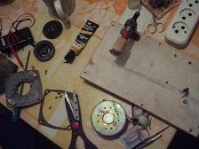
Corrections were made and the hole in the tweeter was recut, then it started...
I decided to measure their resistance in order to calculate the total resistance of the speaker, but the speakers did not show signs of life, the autopsy showed that the patient was given a lethal dose of power - the heart could not withstand... in the sense of the coil (the frame was charred in several places).
Resuscitation of the tweeter
An emergency meeting was opened between me and my wife (thanks to her for understanding me), at which it was proposed to rewind the coils (I have a lot of experience, but not such speakers!). First of all, I had to clean the coil frame from the remnants of the original wire.There were no wires of such thickness, and I had to wind a thicker one (which was found on one of the lying around boards from the radio), a mechanism was invented for winding (thanks to Trudovik from the same school, in secret - I teach computer science there twice a week), on it is visible in the photo, as well as the general creative process!!!
As for how I wound the wire, I don’t know; there was no micrometer then. I wound one turn to another in two layers. There were 70 turns in total. If the wire were thinner, I think it would be wound in three layers. Each layer was coated with Moment.
You see what happened. As a result, the resistance decreased to 4.5 Ohms.
Filtering
Next came the turn of the filter: it was decided to make it of the 2nd order for each link according to the article from RADIO No. 9, 1977, p. 37-38 (I’m doing it now).After rewinding the high-frequency speaker, I decided to try the speakers in action - for this I assembled one speaker, assembled 1st order filters, approximately at the required crossover frequencies (don’t scold me, this is just for testing).
Listening to the speakers
I listened to it on my computer, the sound Creative Audigy SE, I first connected it to a standard 5 W Genius speaker amplifier :), I was not impressed, then I connected it to a homemade amplifier on , which I now use as an amplifier for a subwoofer.As soon as the music started playing (Mobi in the original) I was taken aback - the sound was amazing!!! Maybe my joy for the brainchild is clouding my eyes, but even my wife, who acted as a critic, liked the sound.