We make a television antenna with our own hands. How to make an antenna for a TV with your own hands (55 photos): tips, drawings and installation diagrams Homemade antenna for digital
Making your own antenna is a good idea. You don’t have to spend money on buying a finished product, and you don’t want to attract intruders with a beautiful dish or a high-quality radio installation.
If you have a private house or a summer cottage with a small garage, you can make your own television antenna in literally 20-30 minutes. TV is not only a source of information, but also a special atmosphere of comfort and homeliness.
A television antenna is a device specifically designed for receiving broadcast television signals that are transmitted at frequencies from 41 to 250 MHz in the VHF range, and from 470 to 960 MHz in the UHF group.
There are two types of television antennas:
- Internal – located on top or next to the TV;
- External - installed on the roof or attic of the house.
Outdoor antennas are more complex to manufacture and install, but such devices are necessary for adequate reception in peripheral areas remote from television stations.

Antenna devices are also divided into:
- Active, which are complemented by an amplifier and require connection to an electrical power source;
- Passive, which amplify the signal only due to design features.
An outdoor TV antenna is a high input power device and has a unidirectional radiation intensity so its far end must always face the broadcast station.
Based on the wavelength that television antennas are capable of receiving, they are divided into three groups:
- MV antennas - such devices receive very long meter waves, the size of which can be from 0.5 to 1.5 m;
- UHF antennas - these devices operate in the decimeter range, in which the wavelength is in the range from 15 to 40 cm. It is in this coverage that digital television (DTV) is supplied;
- Broadband antennas are a hybrid design in which both VHF and UHF elements are installed. Such radio installations are used to receive digital and analogue broadcasts simultaneously.
![]()
The most commonly used design is an outdoor television antenna based on a log-periodic dipole matrix. Such products consist of several half-wave elements consisting of metal rods. They act as resonators in which energy is stored by radio waves, which cause electrons to move and create stable waves of oscillatory voltage. An antenna can have a different number of rod elements: the more, the higher its gain.
Another popular design, used primarily for UHF reception, is the reflective TV antenna. Such a device consists of a vertical metal screen with several dipole elements installed in front of it.
The television broadcast bands that must be covered by a single antenna are too wide in frequency, so either separate antennas or combined devices are used for the VHF and UHF bands. In such designs there are two types of elements: long elements that pick up the MF (these are located at the rear of the antenna boom and often function as a log-periodic antenna) and short elements that pick up the UHF broadcast (these are located at the front of the boom).

When you listen to the radio, you notice that local channels can be easily tuned in the FM or VHF range, but you won’t be able to catch distant foreign broadcasts on them; to do this, the receiver needs to be switched to MF and HF mode.
This suggests that meter, medium and short waves are well transmitted over long distances, while ultrashort and decimeter signals have a small coverage area. However, the disadvantage of the UHF range in which our digital television operates is minimized thanks to two things:
- Firstly, the presence of a large number of towers;
- Secondly, the ability of large objects to reflect the signal.
If you live in a private house next to a high-rise building, then it is more correct to point the TV antenna not at a distant tower, but at a neighboring house, which perfectly reflects the waves. The right choice of direction largely determines the qualityTV signal.
Materials and calculations
How and from what items and materials can you make an antenna at home? Let's look at the TOP 5 most interesting options:
- Powerful coaxial cable antenna;
- All-wave antenna made of wire;
- "Butterfly";
- "Eight" or zigzag;
- Antenna made from beer cans.
A tube, rod or wire made of copper or aluminum are excellent materials for making an antenna. They are flexible, bend well and hold their shape well. You can use any conductive metal products: wires, corners, rods, strips, etc.

Coaxial cable has the same properties as copper cable, but is much cheaper, and, in addition, coaxial is also mechanically strong, which is important for antenna design. To save money, you can use pieces of wire that are available in your household or buy them in the hardware store.
First of all, let's decide on the size of the antenna. The antenna cable length (L) is calculated depending on the broadcast frequency. To calculate we need two values:
- The speed of wave propagation in vacuum is ≈ 300 million m/s;
- F – reception frequency (digital TV signal frequencies are usually in the range of 500-800 MHz).
If we take the frequency parameter in MHz, then the desired wavelength value will be in meters. The calculated speed of light parameter is 300. The wavelength in the cable can be calculated using a simple formula:

Calculation example: let digital broadcasting be carried out at an average frequency of 610.5 MHz. Then the average wavelength = 300/610.5 = 0.491 m. This is exactly what the length of the antenna loop should be.
To receive a digital signal, it is not necessary to accurately calculate the wavelength; you can simply make the product design more broadband.
Manufacturing and arrangement
Today, all television is presented in digital format; analogue will soon be completely abandoned. Old antennas practically do not function with DVB signals, so you need to create a decimeter antenna.
Digital TV transmission in DVB-T2 format is carried out in the UHF range, and since the signal is broadcast digitally, its reception will always be in good quality, or it simply cannot be caught, and there will be no signal at all. Interference, distortion or unclear picture - this is typical only for analog television.
DVB (Digital Video Broadcasting) encoding is insensitive to electromagnetic interference, however, if the air is heavily polluted, signal mismatch may occur, which can cause the image to freeze or completely crumble. Therefore, it is more efficient to place the antenna outside the house: outside the window, on the roof, on the balcony.

To reduce the amount of interference, a reflector (reflector) can be built behind the antenna. The simplest materials with a metallic tint are suitable for the antenna design: foil, coffee or juice packaging, tin can, CD, etc. In order for the reflector to have a narrowly targeted effect, the shape of the reflector can be made parabolic. Although this is more relevant for analog receivers, reflectors also help out when the digital signal level is weak.
And the last piece of advice: experienced engineers recommend soldering all antenna connections, and not just twisting or screwing them, as over time they will oxidize and affect the quality of reception. It is better to coat external antennas made by yourself with paint; it will more reliably protect your structure from adverse weather factors.
To connect antenna elements, it is better to use soldering machines with a power of 36-40 watts, flux and soft solders.
Coaxial cable antenna
To create this version of the antenna, you will need about 0.5 m of the most common television cable marked “RK-75”. One end of the insulated wire needs to be stripped to connect to the TV socket (put on the F-connector and an adapter for connecting to the TV), and on the second we will create a round antenna.
Step back 5 cm from the edge and remove the top layer of insulating impregnation compound. Then remove the winding from the central conductor of the cable and tightly twist the remaining wire strands into one bundle.

From this point, measure the next 22 cm and cut through the outer layer of insulation to the shielded foil. Now you need to connect the cable into a ring: to do this, we confidently screw the first prepared end to the newly created cut. That's all - you have in your hands a powerful antenna made of coaxial cable, made by yourself.
Connect it to the TV and start tuning channels. This antenna is considered a good option for receiving digital television. It is better to install the antenna outside the window and on the side of the TV tower, since the walls of the building can drown out the desired signal. You can experiment with its position yourself.
All-wave antenna
A TV antenna can have different shapes. For example, from copper wire with a diameter of 2-5 mm, you can build an all-wave antenna in the form of two versatile elements. Such devices are frequency independent, so they are very popular among summer residents. A CHNA device can be built in literally an hour and receive a good signal level far from television centers.
For this you will need:
- Enameled copper wire;
- 2 metal structures in the shape of an isosceles triangle;
- 2 wooden or plastic slats.
Instead of metal triangles, you can use elastic foil laminate, from which you will need to cut the triangles (or leave the copper coating in a triangular shape).

The width and height of the antenna must be identical. The blades are installed at right angles and fixed with a soldering iron. The CNA antenna cable must be laid to the point of zero potential, which is located at the intersection of the cable with the vertical guide. Moreover, it must be tied with a tie, and not soldered.
The distance between adjacent wire threads should be 25-30 mm, and between the plates - no more than 10 mm. It is better to install the antenna structure inside the window at 150 cm. The signal catcher in the form of two expanded elements, which you just made yourself, will confidently receive all UHF and HF channels. If you live in an area with poor signal levels, it would be advisable to supplement such a device with an amplifier.
A simple antenna for receiving digital TV
Another useful type of home antenna for the dacha is the “butterfly”. This is a very simple design, to create which you will need:
- Board or plywood about 60 cm long and 7 cm wide, thickness about 20 mm;
- Shielded copper wire with a 4 mm core cross-section;
- Coaxial cable “RK-75”;
- Washers, screws, soldering iron.
Below we provide a marking diagram according to which you need to make the base of the butterfly antenna.

After this, prepare 8 pieces of copper wire, each 37.5 cm long. Step back 17.75 cm and remove 2 cm of the insulating layer in the center of each piece. Give them a V-shape so that the ends of the elements are at a distance of 7.5 cm from each other (this shape is considered optimal for high-quality and clear TV signal reception).
The next step is to prepare two more wire elements about 22 cm long. Mark each element into 3 equal parts and strip the wire insulation between the resulting sections.
We will need two more small pieces of wire to connect the antenna to the socket.
Now all that remains is to simply assemble all the prepared elements into a single structure and solder the cable to the plug.
This is how you can easily make your own effective butterfly antenna for receiving digital television.
Figure-of-eight antenna
The next option for creating a simple UHF television antenna is named after the shape of its design, “figure eight” or “zigzag”. Such a device will reliably pick up the signal even in a remote village.
In order to make an outdoor antenna for digital television with your own hands, you will need:
- Amplifier (you can use any old one);
- 2 pieces of copper wire (180 cm each);
- Plate (wood or metal) 15*15;
- TV cable;
- Iron mast for raising the antenna.

First of all, we create the body of the catcher: from copper wire we form two rhombuses with an optimal side size of 45 cm each. We attach the ends of the two elements to the plate: we form a ring from the core and slightly flatten it, screw it with bolts or solder it using a soldering machine.
We connect the amplifier and insert the cable plug into the connector. In general, that's all. All that remains is to install the finished structure on an elevated mast, which must be firmly dug into the ground.
To make an outdoor antenna for a TV, any conductive material of the appropriate cross-section is suitable: copper or aluminum tubes, strips or a profile element with a thickness of 1 to 5 mm. The main thing is to give the antenna body the correct shape.
Beer can antenna
Ether antenna devices can be created from many simple materials that are used in household use, even from ordinary cans in which carbonated drinks are sold. Such a mini-receiver will not be very powerful, but you can pick up about 7 channels, not only in the UHF range, but also in the longer one - VHF.
There is one important condition: the cans must be smooth, not ridged, clean and dry. The essence of this design is very simple: you just need to solder 2 cans to the cable and place them on opposite sides on a wooden base.

The number of cans can be used differently; it is believed that it is optimal to create 3 or 4 lines of cans, since 1-2 lines pick up the signal weakly, and more than 5 lines are difficult to coordinate. In addition to cans, you need to prepare the following materials:
- About 5 meters of ordinary TV cable marked “RK-75”;
- Wooden or plastic base structure;
- Several self-tapping screws, electrical tape, and a soldering iron.
First you need to prepare the TV cable: step back 10 cm from the edge, make a shallow cut and remove the top layer of insulation. Carefully twist the inner braided screen into a single bundle. On the same side of the cable, remove the plastic insulation and expose the central core. A plug must be connected to the opposite end of the cable.
Next, we will need to connect the coaxial cable to the banks. To do this, it is better to use small flea screws for drywall: screw a twisted cable braid to one can, and a copper core to the second can. For better contact, connections can be soldered.

Now you should secure the cans to a wooden base plate. This can be done using ordinary adhesive tape, electrical tape or a glue gun; you can even use an ordinary clothes hanger or any flat structure at hand. The main thing is that the metal cans are of the same shape, the same size (volume) and are located strictly on the same line. The distance between the sheet metal elements, as well as the location of the antenna installation, is selected experimentally.
You can improve the design by creating a grid of several lines with banks, and if there is such an opportunity, then connect an amplifier. If a homemade antenna made from beer cans is placed on the street, then its elements will have to be hidden in larger plastic bottles.
The length of the cable affects the signal attenuation: the longer the cord, the more the on-air transmission is attenuated. This is especially true for receiving meter waves.
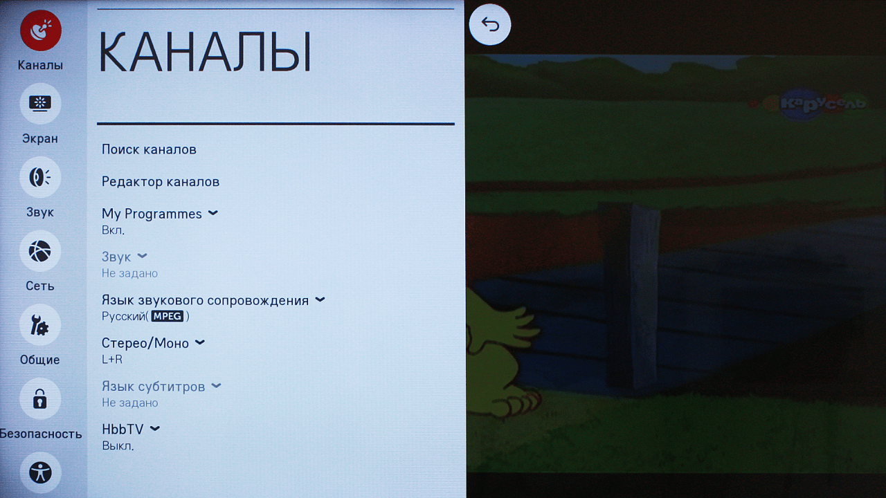
Setting up and searching for channels
Today, digital television offers us as many as 22 television channels in two packages, and in some metropolitan areas there are even more. Setting them up on your TV or set-top box will be quite simple.
In DTV broadcast on 1 frequency, not one channel is broadcast, as it once was on analogue broadcast, but up to 10 channels in one package or multiplex. For example, on frequency 43 you can receive 10 TV channels and 3 radio stations. Therefore, setting up digital broadcasting uses only 2 frequencies. However, the frequency parameter of the channels will be different for different areas.

If you are using a home-made antenna in an area with good signal strength, then there are no special recommendations for setting up channels. You simply turn on the function on your TV "Automatic channel search" and the receiver finds all available channels in digital and analogue air.
If the area of your location is not very favorable for TV broadcasting, and the auto search did not produce results, then you need to perform the following steps:
- Check which direction your antenna is facing. It should be turned towards the television tower or directed towards the nearest high-rise building. If you don't know which way the broadcast base is located, pay attention to your neighbors' antennas (but don't look at the satellite dishes that pick up signals from satellites).
- In channel settings, set a restriction: search only for digital channels (or DTV). Well, if you know the frequency parameter, then you can go into the manual channel tuning mode, use the remote control to dial the channel number on which the package is being broadcast, and a signal level scale in percentage should appear on the display. Change the position of the antenna device and see how the stability of this indicator changes.
The change in signal level when rotating the antenna will not change instantly, but after 5-10 seconds. Therefore, pause when changing the position of the catcher.
When you get the best signal strength, start scanning for digital channels and save your settings. Perform the same algorithm of actions to search for the second multiplex. If the situation is completely sad and not a single method has yielded results, you may need to make the design of your antenna more powerful or supplement it with an amplifier.
Today, almost all homes are connected to cable or satellite television, and almost all channels are in good quality. But what to do if you are just renting an apartment? This is where a homemade antenna for digital television will come to the rescue - as a reliable and inexpensive alternative to the factory one. Read on to see how it is done.
To make this device, you will have to use 550 by 70 mm plywood, several self-tapping screws, and a forty-centimeter copper wire 40 cm long (the central core is 4 mm in diameter).
The base of the product is a board. Next, cut 8 pieces of wire, the length of which is 375 mm, while they should be stripped in the center by 20-30 mm. This is necessary to ensure good contact in signal transmission.
Now, cut out 2 wires, the length of which is 220 mm and, based on the dimensions of the board, they should be cleaned where the connections will be. After this, the remaining wires (eight pieces) need to be bent so that they acquire a “V” shape.

An antenna for digital television is absolutely no different from a regular decimeter antenna.
First, you should start purchasing a special plug, after which it should connect the antenna and cable. This is easy enough. Using a benchtop soldering iron, the plug is attached to the wire. This cable is installed over the bottom connection of the instrument. At this stage, the production of the antenna can be considered completed. It is already ready to be turned on.

An antenna for digital television is absolutely no different from a regular decimeter antenna.
The second method of making a digital television antenna from cans
Here, we will not use a ready-made device as a basis. The device will be completely assembled from available materials. A homemade antenna for digital television is made using:

- wooden trempel;
- adhesive tape or tape;
- soldering iron;
- two tin cans;
- several meters of wire (about 3-5 m);
- plugs.
First, you need to modify the standard television cable. To do this, you need to slightly cut its soft shell. Under the shell you will see a silvery “foil”. This material covers the cable in several layers. For this reason, in order to see the wire itself, you will have to cut about 10 cm from the edge. After this, you should twist the foil layer in order to make a sample of its middle layer by about 10 mm. The reverse end of the cord is equipped with a plug used to connect to the TV.

We're done with the cable, the banks are next. If we talk about sizes, then a tin container with a volume of 750-1000 mm is enough to receive a digital signal. The end of the wire with the “foil” is attached to one can (otherwise, the display of channels will be incorrect). The cable core is screwed onto the second can. It is preferable to connect the cable and cans by soldering. If the wire is secured with tape, most likely the product will not work.
The only option for using such material is when the cans are installed on top of the trempel. However, even here one cannot deviate from the technology of application. Namely, the arrangement of the cans should form a straight line. Tin containers should be located at a distance of about 7-8 cm from one another.
That's all, the homemade antenna for digital television is ready. Now you can start searching for a suitable signal and securing your device. Such an antenna will allow you to view several channels, up to 10-15, if the signal is not password protected.
Video: homemade antenna for digital television
Despite the rapid development of satellite and cable television, the reception of terrestrial television broadcasts still remains relevant, for example, for places of seasonal residence. It is not at all necessary to buy a finished product for this purpose; a home UHF antenna can be assembled with your own hands. Before moving on to considering the designs, we will briefly explain why this particular range of the television signal was chosen.
Why DMV?
There are two good reasons to choose designs of this type:
- The thing is that most channels are broadcast in this range, since the design of repeaters is simplified, and this makes it possible to install a larger number of unattended low-power transmitters and thereby expand the coverage area.
- This range is selected for digital broadcasting.
Indoor TV antenna “Rhombus”
This simple, but at the same time, reliable design was one of the most common in the heyday of on-air television broadcasting.
Rice. 1. The simplest homemade Z-antenna, known under the names: “Rhombus”, “Square” and “People’s Zigzag”As can be seen from the sketch (B Fig. 1), the device is a simplified version of the classic zigzag (Z-design). To increase sensitivity, it is recommended to equip it with capacitive inserts (“1” and “2”), as well as a reflector (“A” in Fig. 1). If the signal level is quite acceptable, this is not necessary.
The material you can use is aluminum, copper, and brass tubes or strips 10-15 mm wide. If you plan to install the structure outdoors, it is better to abandon aluminum, since it is susceptible to corrosion. Capacitive inserts are made of foil, tin or metal mesh. After installation, they are soldered along the circuit.
The cable is laid as shown in the figure, namely: it did not have sharp bends and did not leave the side insert.
UHF antenna with amplifier
In places where a powerful relay tower is not located in relative proximity, you can raise the signal level to an acceptable value using an amplifier. Below is a schematic diagram of a device that can be used with almost any antenna.
 Rice. 2. Antenna amplifier circuit for the UHF range
 List of elements:
- Resistors: R1 – 150 kOhm; R2 – 1 kOhm; R3 – 680 Ohm; R4 – 75 kOhm.
- Capacitors: C1 – 3.3 pF; C2 – 15 pF; C3 – 6800 pF; C4, C5, C6 – 100 pF.
- Transistors: VT1, VT2 – GT311D (can be replaced with: KT3101, KT3115 and KT3132).
Inductance: L1 - is a frameless coil with a diameter of 4 mm, wound with copper wire Ø 0.8 mm (2.5 turns must be made); L2 and L3 are high-frequency chokes 25 µH and 100 µH, respectively.
If the circuit is assembled correctly, we will get an amplifier with the following characteristics:
- bandwidth from 470 to 790 MHz;
- gain and noise factors – 30 and 3 dB, respectively;
- the value of the output and input resistance of the device corresponds to the RG6 cable – 75 Ohm;
- the device consumes about 12-14 mA.
Let's pay attention to the method of power supply; it is carried out directly through the cable.
This amplifier can work with the simplest designs made from improvised means.
Indoor antenna made from beer cans
Despite the unusual design, it is quite functional, since it is a classic dipole, especially since the dimensions of a standard can are perfectly suitable for the arms of a decimeter range vibrator. If the device is installed in a room, then in this case it is not even necessary to coordinate with the cable, provided that it is not longer than two meters.

Designations:
- A - two cans with a volume of 500 mg (if you take tin and not aluminum, you can solder the cable instead of using self-tapping screws).
- B – places where the cable shielding is attached.
- C – central vein.
- D – place of attachment of the central core
- E – cable coming from the TV.
The arms of this exotic dipole must be mounted on a holder made of any insulating material. As such, you can use improvised things, for example, a plastic clothes hanger, a mop bar or a piece of wooden beam of appropriate size. The distance between the shoulders is from 1 to 8 cm (selected empirically).
The main advantages of the design are fast production (10 - 20 minutes) and quite acceptable picture quality, provided there is sufficient signal power.
Making an antenna from copper wire
There is a design that is much simpler than the previous version, which only requires a piece of copper wire. We are talking about a narrow band loop antenna. This solution has undoubted advantages, since in addition to its main purpose, the device plays the role of a selective filter that reduces interference, which allows you to confidently receive a signal.
 Fig.4. A simple UHF loop antenna for receiving digital TV
 For this design, you need to calculate the length of the loop; to do this, you need to find out the frequency of the “digit” for your region. For example, in St. Petersburg it is broadcast on 586 and 666 MHz. The calculation formula will be as follows: L R = 300/f, where L R is the length of the loop (the result is presented in meters), and f is the average frequency range, for St. Petersburg this value will be 626 (the sum of 586 and 666 divided by 2). Now we calculate L R, 300/626 = 0.48, which means the length of the loop should be 48 centimeters.
If you take a thick RG-6 cable with braided foil, it can be used instead of copper wire to make a loop.
Now let's tell you how the structure is assembled:
- A piece of copper wire (or RG6 cable) with a length equal to L R is measured and cut.
- A loop of suitable diameter is folded, after which a cable leading to the receiver is soldered to its ends. If RG6 is used instead of copper wire, then the insulation from its ends is first removed, approximately 1-1.5 cm (the central core does not need to be cleaned, it is not involved in the process).
- The loop is installed on the stand.
- The F connector (plug) is screwed onto the cable to the receiver.
Note that despite the simplicity of the design, it is most effective for receiving “digits”, provided that the calculations are carried out correctly.
Do-it-yourself MV and UHF indoor antenna
If, in addition to UHF, there is a desire to receive MF, you can assemble a simple multiwave oven, its drawing with dimensions is presented below.

To amplify the signal, this design uses a ready-made SWA 9 unit; if you have problems purchasing it, you can use a home-made device, the diagram of which was shown above (see Fig. 2).
It is important to maintain the angle between the petals; going beyond the specified range significantly affects the quality of the “picture”.
Despite the fact that such a device is much simpler than a log-periodic design with a wave channel, it nevertheless shows good results if the signal is of sufficient power.
DIY figure eight antenna for digital TV
Let's consider another common design option for receiving “digits”. It is based on the classic scheme for the UHF range, which, because of its shape, is called “Figure Eight” or “Zigzag”.
 Rice. 6. Sketch and implementation of the digital eight
 Design dimensions:
- outer sides of the diamond (A) – 140 mm;
- internal sides (B) – 130 mm;
- distance to the reflector (C) – from 110 to 130 mm;
- width (D) – 300 mm;
- the pitch between the rods (E) is from 8 to 25 mm.
The cable connection location is at points 1 and 2. The material requirements are the same as for the “Rhombus” design, which was described at the beginning of the article.
Homemade antenna for DBT T2
Actually, all of the examples listed above are capable of receiving DBT T2, but for variety we will present a sketch of another design, popularly called “Butterfly”.

The material can be used as plates made of copper, brass, aluminum or duralumin. If the structure is planned to be installed outdoors, then the last two options are not suitable.
Bottom line: which option to choose?
Oddly enough, the simplest option is the most effective, so the “loop” is best suited for receiving a “digit” (Fig. 4). But, if you need to receive other channels in the UHF range, then it is better to stop at “Zigzag” (Fig. 6).
The antenna for the TV should be directed towards the nearest active repeater, in order to select the desired position, you should rotate the structure until the signal strength is satisfactory.
If, despite the presence of an amplifier and reflector, the quality of the “picture” leaves much to be desired, you can try installing the structure on a mast.

In this case, it is necessary to install lightning protection, but this is a topic for another article.
The lucky owners of a country house or dacha have more than once had to face a problem: in areas remote from the city there is simply no connection so that you can use a mobile phone or watch TV. If modern mobile phones are already equipped with powerful hidden antennas for receiving signals, then the signal for watching TV is more difficult. The only solution is an external antenna. Moreover, you don’t have to run to the store to buy expensive equipment - you can easily make an antenna for your dacha (using a GSM signal) with your own hands!
If your dacha already has a weak signal and your TV has poor reception of 1-2 channels, then you can improve the quality of reception in a matter of minutes. First, you should understand that the stations sending the signal are located at a distance from your dacha. And your TV is now receiving a random signal that was not directed to a specific receiver. In order for the signal to become better, you need an antenna (receiver) that will transmit the signal directly to the TV.
An antenna can be made either from an old antenna or from things that are completely unsuitable at first glance - scrap materials.
In the first option, we’ll look at how to make a classic antenna for a summer house with your own hands
1) Wire. You should choose a high-quality conductor based on the following calculation: 1.5-2 meters per antenna, 5-6 meters (depending on your interior) at the distance from the antenna to the TV. Let's assume that you have chosen a wire whose diameter is 1.5 mm.
2) The outer part of the antenna. Made from prepared wire. 1-1.5 meters need to be twisted into a ring, the diameter of which will be from 356 mm. up to 450 mm.
3) Internal part of the antenna. It is necessary to make a second ring from wire, correspondingly smaller than the first (about 180 mm).
4) The finished rings - this is the basis of the future antenna - need to be fixed on a small piece of plywood. Instead of plywood, you can use any suitable piece of wood. The tree should not overlap the rings and should not dangle so that the entire antenna is clearly fixed to the roof.
5) The finished structure must be directed in rings in the direction of the signal source. No doubt the signal will be strong towards the city. At this stage, ask for help: you need to turn the antenna in different directions and check where the signal will be better. Once you find the best option, your antenna is finally ready!
Making an antenna from beer cans
There are many ways to make a simple and high-quality (for a high-quality signal) television antenna for your summer cottage. We looked at a way to create a “classical” antenna, but there are also non-standard solutions. For example, you can quickly make an antenna from old tin cans (Coca-Cola or beer). Such an antenna is in no way inferior in characteristics to store-bought innovations, plus it will help the owner of the dacha save money.
To create an antenna you will need a couple of 0.5 liter tin cans, rosin, tin, a little electrical tape, simple tape, a clothes hanger (must be plastic!) and 5-6 meters of television cable (which, by the way, does not have to be new!) .

- To the first can you need to solder a TV cable (braided, peeled to 15-20 mm), and to the other - the central core (of the same cable). It will be easier to dip the soldering iron in tin and rosin, and then tin the wire. Conductors should be insulated with electrical tape!
- Attach the jars to the hanger, to its bottom.
- Connect the plug to one side of the cable
- Connect the plug to the TV. The antenna is ready!
Such an antenna can also catch the “meter” range if you use cans with a volume of 1.0 liter rather than 0.5 liters. If in the first case it was necessary to rotate the antenna in order to “catch” a good signal, then in the case of tin cans you should change the distance between them (the cans) on the hanger. Place the antenna itself near a window or balcony.
Thus, there are many ways to make an antenna for your dacha with your own hands and provide yourself and your loved ones with a pleasant viewing of television programs in the fresh air. “Homemade” antennas are in no way inferior to store-bought ones and can become a 100% substitute for them (especially since it will be easier and cheaper to make a new antenna than to buy a store-bought one in case of a breakdown)!
It was a very prestigious matter and indicated a high level of craftsman; in our age, stuffed with all kinds of electronics, interest in “homemade” antennas does not subside and many craftsmen make TV antennas themselves. Manufacturers of both industrial equipment and various entrepreneurs have adapted to the changed conditions for receiving television signals by simply connecting modern electronic components to standard antenna designs, ignoring the fact that the main thing in the normal operation of any antenna is and will be its interaction and coordination with the receiving signal. This is what the zigzag antenna, proposed back in 1961 by engineer Kharchenko, has.
My house is located five kilometers from the transmitting repeater, the outdoor TV antenna requires major repairs and reconstruction, but it is very difficult for a 67-year-old disabled person to get to the ridge on the old slate roof. I’ve known the “eight” for a long time and first-hand, which is why its indoor version was chosen until better times. To know the channels on which the multiplexes of my repeater operate, I visited the resource, inserted it into the data of my channels and received a sketch with the dimensions of a digital individual antenna.
An excellent material for an antenna is copper, in the absence of which I resorted to a trick. I found a meter-long piece of old television cable,

from which with a knife

carefully removed the top shell,

assembled copper screen braid into an accordion

and freed it from the central core with its shell. Instead, I inserted an aluminum wire with a diameter of 3 mm of the size I needed,

one end of the braid is soldered

and pulled it tightly onto the aluminum wire - the result was a copper rod with a diameter of slightly more than 4 mm.

Using pliers,

and square

I bent two squares in the shape of a figure eight, but did not bend the last corner yet.

I still have a thin TV cable about three meters,

I decided to use it to connect the antenna to the TV. At the last sides of the square, I again assembled the braid into an accordion, in the lower corner of the antenna with an awl

I made a hole and pulled the tip of the cable inside the braid so that it was together with the aluminum wire, but two centimeters longer. I removed the top sheath by two centimeters from the cable, pulled the braid onto the aluminum wire along with the cable, twisted the end of the braid with the cable screen and soldered it.

I bent the last corner, shortened the tinned ends of the antenna to 5 millimeters and soldered them together. The central wire was soldered to the opposite inner corner of the figure eight, maintaining a distance of 10 millimeters. The antenna, perfectly matched with the cable, is ready,